Methods and apparatus for configuring a data analyzer

a data analyzer and configuration method technology, applied in the field of data analyzers, can solve the problems of inexperienced users defining the configuration incorrectly, complex definitions, time-consuming and other problems, and achieve the effects of simple configuration of the data analyzer, short period of time, and convenient diagnosis of the operation of the machine train

Active Publication Date: 2017-03-02
BAKER HUGHES HLDG LLC
View PDF2 Cites 2 Cited by
  • Summary
  • Abstract
  • Description
  • Claims
  • Application Information

AI Technical Summary

Benefits of technology

The patent describes a method for configuring a data analyzer and an interactive graphical representation of a machine train for diagnosis and analysis. The technical effects include improved ease of use and accuracy of data analysis and diagnosis of machine train performance. The method and system use a user interface to display and select components of a machine train, allowing for quick and easy setup of the data analyzer. The interactive graphical representation of the machine train enables analysis of individual components and the overall performance of the entire machine train. The generated configuration file facilitates operation of the machine train using the data analyzer. Overall, the data analyzer and method described in the patent improve efficiency and accuracy in data analysis and machine train diagnosis.

Problems solved by technology

However, at least some known data analyzers may use complex computer software such that inexperienced users may define the configuration incorrectly.
The complexity of known data analyzer computer software may also require that the machine and data analyzer configurations be defined before performing the diagnostic test.
However, such definitions may be time-consuming and may also be complex.
Furthermore, at least some known methods of defining a data analyzer configuration rely on detailed English-language descriptions of the machine and data analyzer, which may cause a non-English speaker to define the configuration inaccurately.
Defining the configuration inaccurately can result in obtaining unusable diagnostic data collection.
As such, the use and accuracy of known diagnostic systems may be limited.

Method used


Image

  • Methods and apparatus for configuring a data analyzer
  • Methods and apparatus for configuring a data analyzer
  • Methods and apparatus for configuring a data analyzer

Examples


Embodiment Construction

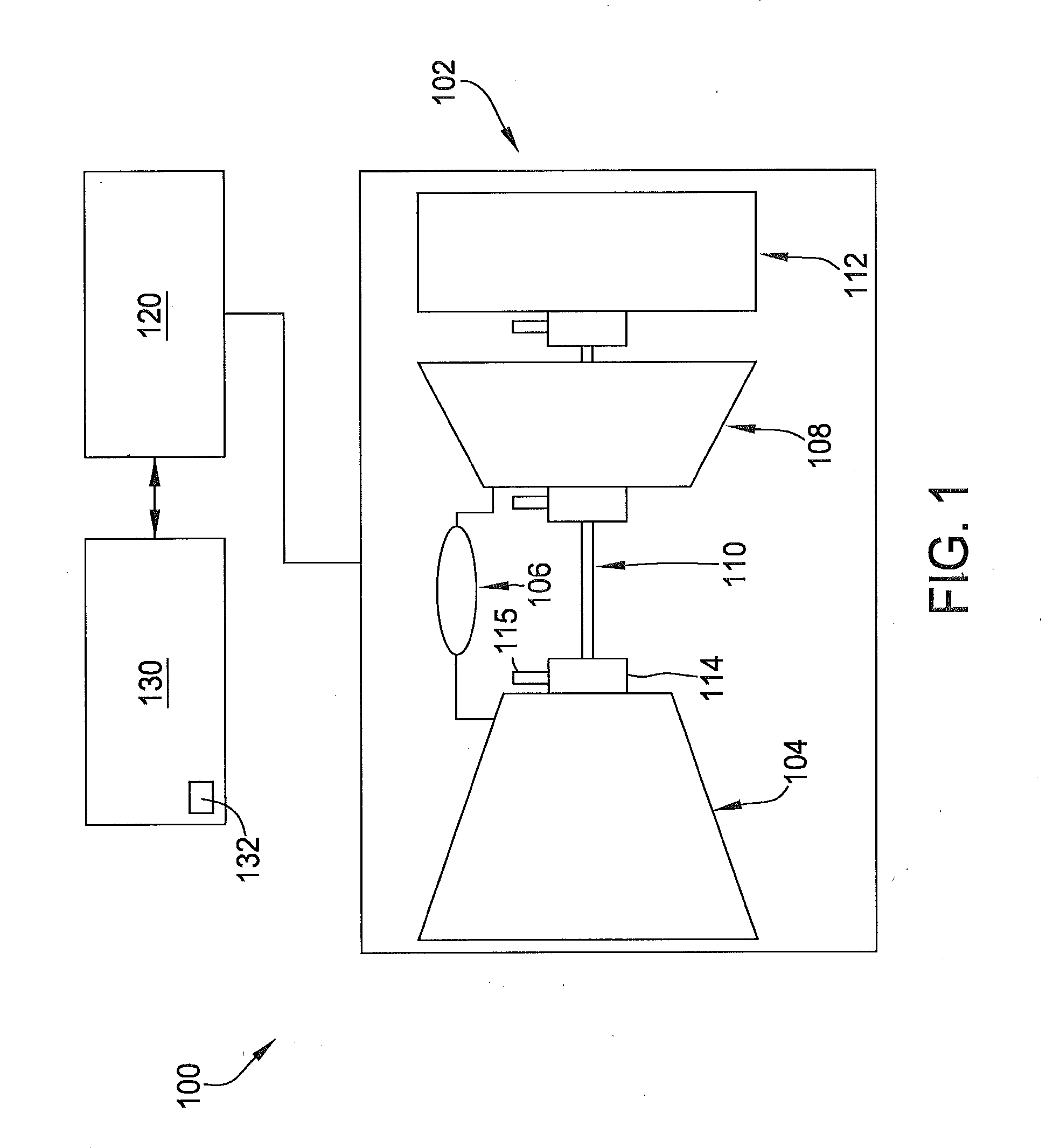
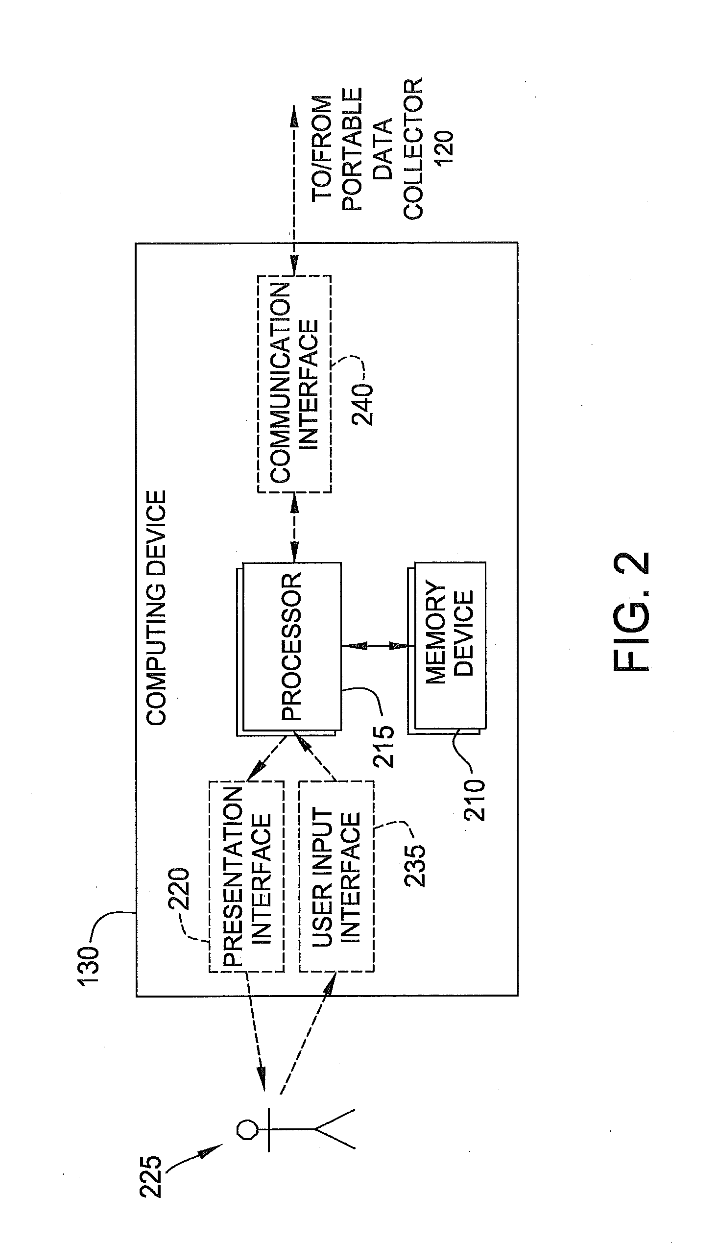
[0012]The apparatus and methods described herein facilitate configuring a data analyzer to enable diagnostic tests to be performed on a machine. A data analyzer configuration tool, operating on a computing device, displays various graphical representations of components of the data analyzer and the machine and allows a user to configure both the data analyzer and the machine on the tool to represent the physical equipment. After the data analyzer and the machine are configured, the data analyzer configuration tool generates a configuration file used by the data analyzer to perform the diagnostic test.

[0013]As used herein, the term “component” is an element of the data analyzer or the machine to be monitored in accordance with the diagnostic system. Motors, engines, gearboxes, pumps, fans, card types and like items are examples of components. As used herein, the term “configuration” is a detailed definition of the data analyzer or the machine comprising one or more components coupled...


PUM


Abstract

A method for configuring a data analyzer is provided. The method comprises displaying to a user, on a presentation interface coupled to a processor, a graphical representation of at least a portion of the data analyzer. A data analyzer configuration for the data analyzer is then generated using a user input interface, which is coupled to the presentation interface and the processor. The presentation interface then displays to the user a plurality of selectable machine train components. The method also comprises generating, using the user input interface, an interactive graphical representation of a machine train including at least one of the selectable machine train components. Using the processor, a configuration file is generated based on the data analyzer configuration and the graphical representation of the machine train. The configuration file facilitates diagnosing operation of the machine train using the data analyzer.

Description

CROSS REFERENCE TO RELATED APPLICATION[0001]This application is a continuation of U.S. patent application Ser. No. 13 / 728,302, entitled “Methods and Apparatus for Configuring a Data Analyzer”, filed Dec. 27, 2012 and is hereby incorporated by reference in its entirety.BACKGROUND OF THE INVENTION[0002]The embodiments described herein relate generally to a data analyzer for use in monitoring a machine, and, more particularly, to methods and apparatus for configuring the data analyzer.[0003]When operating machinery, it may be necessary or advantageous to monitor the operating conditions of the machine to confirm the machine is operating within pre-determined operating limitations. At least some known monitoring and diagnostic systems use transducers, or probes, to collect operational data from the machine during a diagnostic test that is compared to stored pre-determined operating limitations to determine if the machine is operating normally. Data collected during the diagnostic test i...

Claims


Application Information

Patent Timeline
Patent Type & Authority Applications(United States)
IPC IPC(8): G06F3/0482G06F3/0486G05B23/02G06F3/0481
CPCG06F3/0482G06F3/04817G05B23/0272G05B23/0216G06F3/0486G05B19/41885G05B2219/32404Y02P90/02G06F3/0481G06F13/10
Inventor ALLDREDGE, GREGORY MARKFROGGET, DARYL RONALDMARSHALL, DONALD EVANABBOTT, BRIAN DEANTAPPAN, JACQUELINE MARIEKINGHAM, JOHN WHITNEY
Owner BAKER HUGHES HLDG LLC
Why Eureka
Try Eureka