
Underwater high-resolution side-looking acoustic imaging system and method thereof

A high-resolution, imaging system technology, applied in the field of underwater acoustic imaging, can solve the problem of low mapping efficiency of the imaging system

Inactive Publication Date: 2010-09-08
INST OF ACOUSTICS CHINESE ACAD OF SCI
View PDF5 Cites 20 Cited by
  • Summary
  • Abstract
  • Description
  • Claims
  • Application Information

AI Technical Summary

Problems solved by technology

[0003] The purpose of the present invention is to overcome the deficiencies of the prior art, such as the limitation of the moving speed of the sonar array by the length of multiple sub-arrays, and the low mapping efficiency of the imaging system, the present invention provides an underwater high-resolution side-view Acoustic imaging system and method

Method used


Image

  • Underwater high-resolution side-looking acoustic imaging system and method thereof
  • Underwater high-resolution side-looking acoustic imaging system and method thereof
  • Underwater high-resolution side-looking acoustic imaging system and method thereof

Examples


Embodiment Construction

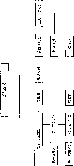
[0063] An underwater high-resolution side-view acoustic imaging system and method of the present invention will be described in detail below in conjunction with the accompanying drawings. DETAILED DESCRIPTION OF THE PREFERRED EMBODIMENT Taking the center frequency as f 1 and f 2 , a side-looking synthetic aperture sonar system with bandwidth B as an example. The working process of the system is described as follows. In order to make the description clear, the description process of this embodiment focuses on the implementation process of this patent, and the efficiency of the digital signal processing algorithm in this embodiment can be improved in various ways. For ease of description, in this embodiment, the first transmitting array 1 and the second transmitting array 2 use two sets of acoustic signals with different frequency bands. In century applications, the first transmitting array 1 and the second transmitting array 2 may use two sets of signals with different encod...


PUM


Abstract

The invention provides an underwater high-resolution side-looking acoustic imaging system. The system comprises a transmitting array, a receiving array and a receiver, wherein the receiver comprises a signal conditioning and acquisition functional module, a data transmission module and a data processing module, the signal conditioning and acquisition functional module is used for filtering and amplifying underwater acoustic signals and converting analog signals into digital signals, the data processing module also comprises a memory module, an image reconstruction module, a movement error estimation and compensation processing module and an image display module. The system is characterized in that: the transmitting array is a transmitting array group which consists of two transmitting arrays, and is used for transmitting acoustic signals with different frequency bands, and each transmitting array is driven by a transmitter. The invention also puts forward a method for utilizing the transmitting array group to carry out underwater high-resolution side-looking acoustic imaging. The invention has the advantages that: the limitation of the length of a plurality of sub-arrays of a sonar array on the moving speed is reduced, and thereby the surveying efficiency of the imaging system is increased.

Description

technical field [0001] The invention relates to the field of underwater acoustic imaging, in particular to an underwater high-resolution side-view acoustic imaging system and method. Background technique [0002] Since the propagation loss of sound waves in water is much smaller than that of light and electromagnetic waves, the use of sound waves is the main means of underwater environment detection. Resolution is an important assessment index for underwater acoustic imaging equipment. For traditional side-scan sonars, the range resolution can be obtained by using broadband signals, while the azimuth resolution is related to factors such as the length of the acoustic transducer array, the frequency of the acoustic signal, and the target distance. The longer the length of the acoustic transducer, the higher the azimuth resolution; the farther the imaging target is, the lower the azimuth resolution; the higher the frequency of the acoustic signal used, the higher the azimuth ...

Claims


Application Information

Patent Timeline
Patent Type & Authority Applications(China)
IPC IPC(8): G01S15/89
CPCG01S15/8904
Inventor 刘维刘纪元黄海宁张春华
Owner INST OF ACOUSTICS CHINESE ACAD OF SCI
Learn More