Lifting device for elevator, elevator car frame, and lifting method for elevator
A car frame and elevator technology, which is applied in the direction of lifting equipment, elevators, transportation and packaging in mines, can solve the problems of increased cost and time-consuming assembly, and achieve the effect of increasing assembly time.
- Summary
- Abstract
- Description
- Claims
- Application Information
AI Technical Summary
Problems solved by technology
Method used
Image

Examples
Embodiment approach 1
[0111] (1. Outline of the lifting device 100)
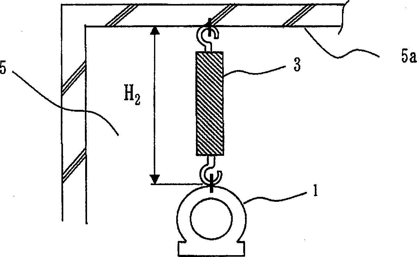
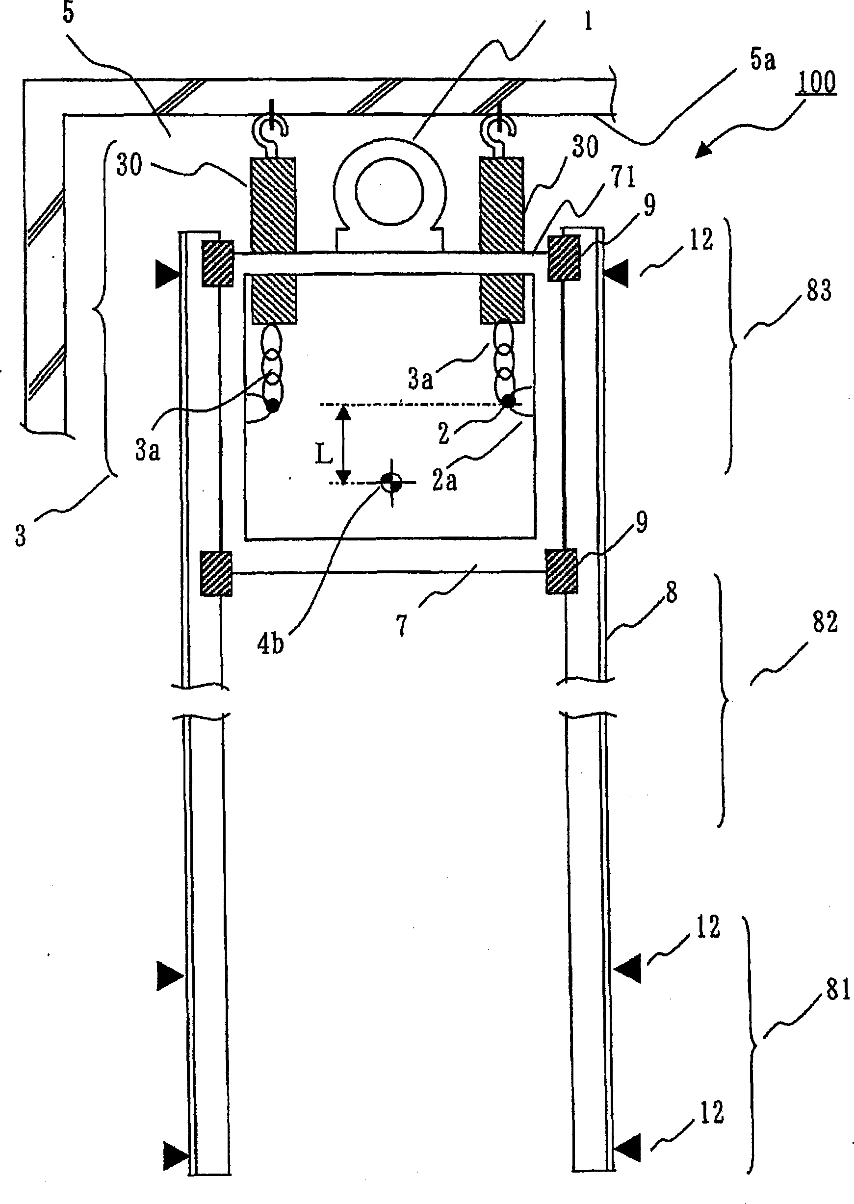
[0112] In Embodiment 1, an elevator hoisting device for hoisting a heavy load in an elevator hoistway will be described. figure 1 It is a figure explaining the disadvantage of the case of directly lifting the heavy object 1 which is a lifting object. figure 2 It is a figure explaining the structure of the lifting apparatus 100 of this Embodiment 1. figure 2 Indicates after the upgrade is complete.
[0113] Such as figure 1 As shown, in the case of lifting a heavy object 1 (such as a tractor), when temporarily installing a crane 3 (such as a winch) on the ceiling of the hoistway 5 (shaft top 5a) and hoisting the heavy object 1, for the heavy object 1. It is equivalent to the height of the crane 3 itself (lifting margin H 2 ) cannot be increased. Therefore, there are cases where the size of the hoistway becomes longer by an amount equivalent to the lifting margin H 2 . In Embodiment 1, for not using the boost margin H 2...
Embodiment approach 2
[0194] In Embodiment 1, the crane main body 30 is installed in the hoistway top 5a. On the other hand, in Embodiment 2, the case where the crane main body 30 is installed in the car frame 7 is demonstrated.
[0195] Figure 18 It is a figure which shows the case (Embodiment 1) in which the crane main body 30 is installed in the hoistway ceiling 5a. in comparison, Figure 19 It is a figure which shows the state where the crane main body 30 is attached to the car frame 7. As shown in FIG. also, Figure 20 with Figure 21 It is a perspective view of a case where the crane main body 30 is attached to the car frame 7 . Figure 20 with Figure 9 correspond, Figure 21 with Figure 11 correspond. Such as Figure 20 or Figure 21 As shown, the crane main body 30 is attached to the car vertical column 7 b of the car frame 7 . That is, in Figure 20 or Figure 21 Among them, the crane main body 30 has a chain 35a whose end is a hook (not shown). This hook is hooked to the...
PUM
 Abstract
Description
Claims
Application Information
 - R&D
- Intellectual Property
- Life Sciences
- Materials
- Tech Scout
- Unparalleled Data Quality
- Higher Quality Content
- 60% Fewer Hallucinations
Browse by: Latest US Patents, China's latest patents, Technical Efficacy Thesaurus, Application Domain, Technology Topic, Popular Technical Reports.
© 2025 PatSnap. All rights reserved.Legal|Privacy policy|Modern Slavery Act Transparency Statement|Sitemap|About US| Contact US: help@patsnap.com