
Electronic package and fabrication method thereof

A technology for electronic packaging and manufacturing method, which is applied in the manufacturing of electrical components, electrical solid-state devices, semiconductor/solid-state devices, etc. Miniaturization, high electrical performance, cost saving effect

Pending Publication Date: 2022-05-13
SILICONWARE PRECISION IND CO LTD
View PDF0 Cites 0 Cited by
  • Summary
  • Abstract
  • Description
  • Claims
  • Application Information

AI Technical Summary

Problems solved by technology

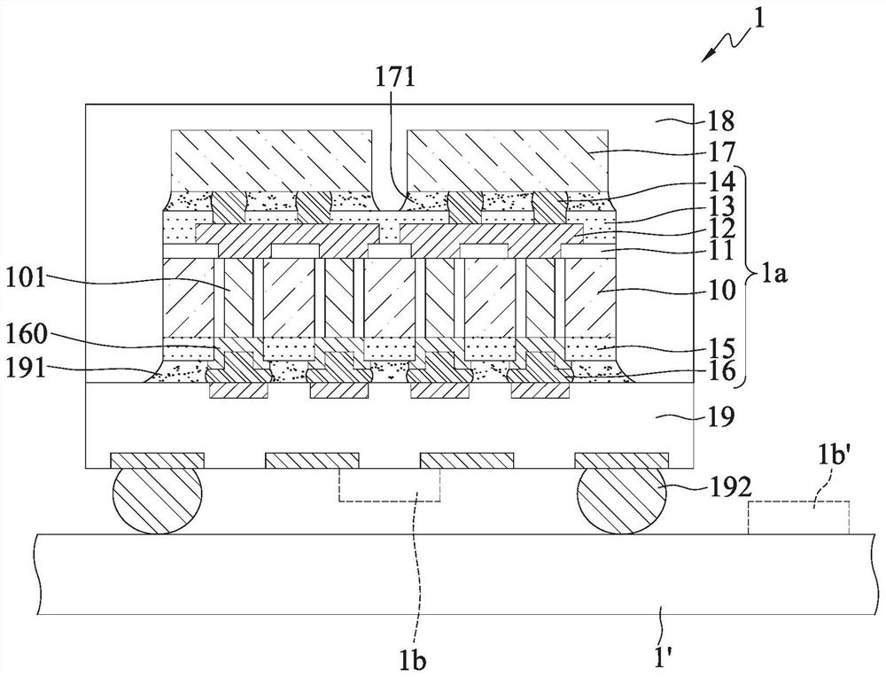
[0010] However, with the demand of the consumer market, the functional requirements of terminal products are becoming more and more diverse, so more and more semiconductor chips 17 are connected to the packaging substrate 19, so the demand for auxiliary functional components 1b matching it is greatly increased. As a result, there is no extra space on the lower side of the packaging substrate 19 for disposing more auxiliary functional components 1b, resulting in a single package structure 1 that can no longer meet the requirements of today's terminal products, such as light and thin, low power consumption, and high electrical performance.
[0011] In addition, although the auxiliary functional element 1b can be integrated into the semiconductor chip 17, the packaging structure 1 needs to be redesigned, which not only increases the production cost, but also increases the size of the semiconductor chip 17, so it is difficult to meet the miniaturization requirements

Method used


Image

  • Electronic package and fabrication method thereof
  • Electronic package and fabrication method thereof
  • Electronic package and fabrication method thereof

Examples


Embodiment Construction

[0088] Embodiments of the present invention are described below through specific examples, and those skilled in the art can easily understand other advantages and effects of the present invention from the content disclosed in this specification.

[0089] It should be noted that the structures, proportions, sizes, etc. shown in the drawings of this specification are only used to match the content disclosed in the specification for the understanding and reading of those skilled in the art, and are not used to limit the conditions for the implementation of the present invention , so it has no technical substantive meaning, and any modification of structure, change of proportional relationship or adjustment of size shall still fall within the scope of the disclosure of the present invention without affecting the functions and objectives of the present invention. The technical content must be within the scope covered. At the same time, terms such as "above", "first", "second", "thi...


PUM


Abstract

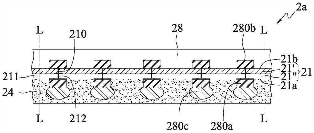
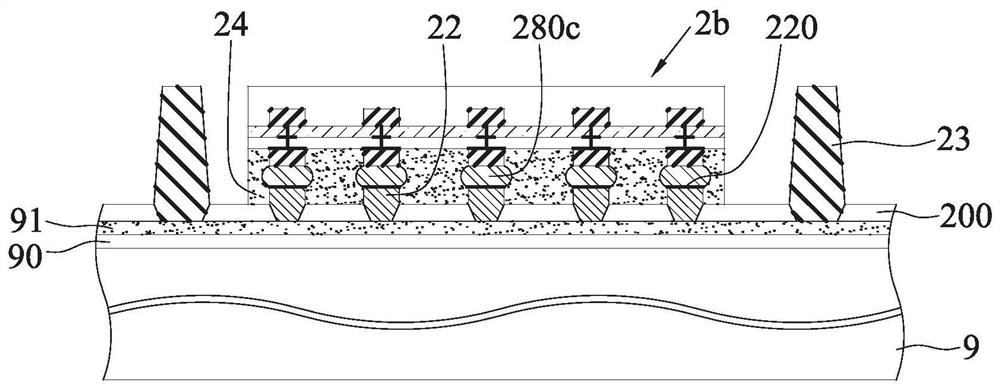
The invention relates to an electronic packaging part and a manufacturing method thereof, which are used for embedding an electronic structure serving as an auxiliary functional element and a plurality of conductive columns in a coating layer and arranging an electronic part on the coating layer so as to be matched with the electronic part at a short distance to carry out electrical transmission.

Description

technical field [0001] The invention relates to an electronic package and its manufacturing method, especially to an electronic package with auxiliary functional elements and its manufacturing method. Background technique [0002] With the vigorous development of the electronic industry, electronic products are gradually moving towards multi-functional and high-performance trends. For example, auxiliary functional components such as integrated voltage regulators (IVR) are embedded in high-performance processors to improve efficiency, such as switching frequency , reduce power consumption, improve reliability, and even reduce manufacturing costs. At the same time, technologies currently used in the field of chip packaging include, for example, Chip Scale Package (CSP for short), Direct Chip Attached (DCA for short) or Multi-Chip Module (Multi-Chip Module, Flip-chip packaging modules such as MCM for short, or three-dimensional integrated circuit (3D IC) chip stacking technolo...

Claims


Application Information

Patent Timeline
Patent Type & Authority Applications(China)
IPC IPC(8): H01L23/31H01L21/50H01L21/56
CPCH01L23/3107H01L21/50H01L21/568H01L2224/73204H01L2224/32225H01L2224/16225H01L2924/15311H01L2924/181H01L2224/0401H01L2224/97H01L2224/16237H01L2224/73259H01L2224/92224H01L2224/81005H01L2224/83005H01L2224/73104H01L2224/131H01L2224/94H01L2224/0557H01L2224/13082H01L2224/13147H01L2224/04105H01L2224/12105H01L2224/48227H01L2224/92125H01L24/19H01L24/96H01L24/13H01L24/16H01L24/32H01L24/48H01L24/73H01L24/92H01L2224/214H01L2224/2518H01L24/97H01L23/5389H01L23/49816H01L23/5385H01L21/6835H01L2221/68359H01L2221/68345H01L2221/68372H01L21/561H01L25/50H01L25/03H01L2924/00012H01L2924/00H01L2224/81H01L2224/83H01L2924/014H01L2924/00014H01L2224/11H01L2224/27H01L2224/85H01L21/4853H01L21/4857H01L21/563H01L23/3157H01L23/5381H01L23/5383H01L23/5386H01L25/0655H01L2224/16227H01L2924/18161H01L21/565H01L23/49822H01L24/81H01L25/105H01L2224/16238H01L2224/81801H01L2225/1035H01L2225/1041H01L2225/1058H01L2225/107H01L2924/182
Inventor 陈玮真许智勋许元鸿林志男林长甫江东升黄致明陈宜兴
Owner SILICONWARE PRECISION IND CO LTD
Learn More