Gas turbine

A gas turbine, hot gas technology, applied in the direction of gas turbine devices, mechanical equipment, engine components, etc., can solve the problems of cooling air loss pressure, no solution provided, unable to return to the combustion chamber, etc., and achieve the effect of improving efficiency

Inactive Publication Date: 2006-06-07
SIEMENS AG
View PDF1 Cites 0 Cited by
  • Summary
  • Abstract
  • Description
  • Claims
  • Application Information

AI Technical Summary

Problems solved by technology

[0004] This cooling air cannot be used for combustion smoothly, because the cooling air loses too much pressure on its cooling path, and may not be able to return to the combustion chamber, where it can support combustion
[0005] The prior art described above does not provide a solution on how to use the cooling air which cools at least the guide vanes and the guide ring also for combustion

Method used


Image

  • Gas turbine
  • Gas turbine

Examples


Embodiment Construction

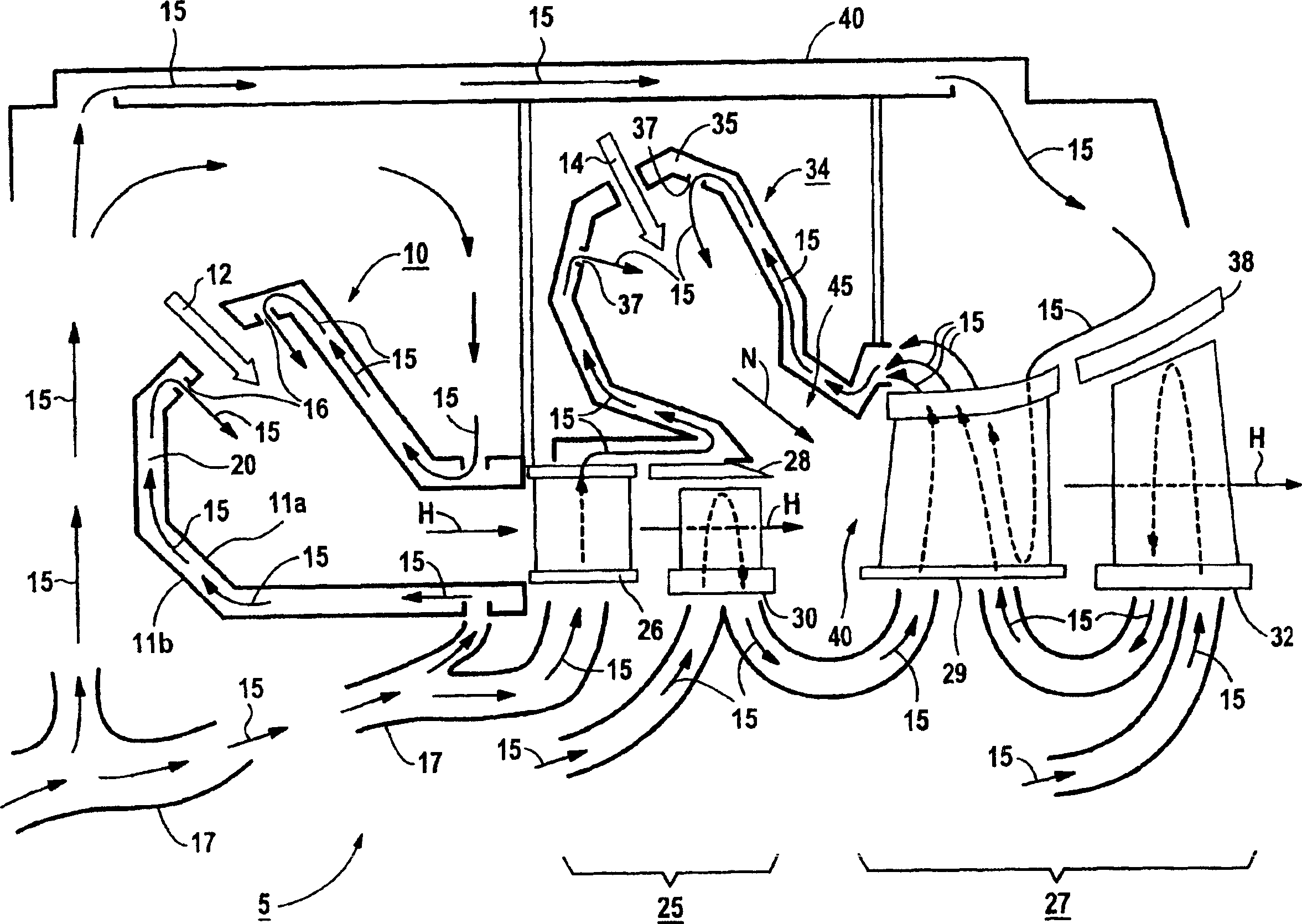
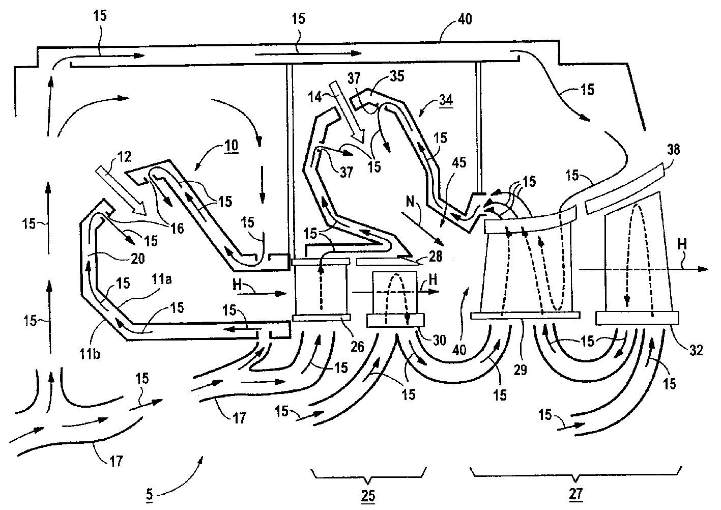
[0031] The gas turbine 5 comprises a main combustion chamber 10 , the combustion chamber of which is closed off by a combustion chamber wall 11 a. The main combustion chamber 10 is separated from the outside by a combustion outer wall 11b, so that a cooling air channel 20 is formed between the combustion chamber wall 11a and the combustion outer wall 11b.

[0032] During the working process of the gas turbine 5, the compressor gas mixture 12 produced by the compressor is sent into the main combustion chamber 10, where it is burned by an unillustrated burner located in the main combustion chamber 10 to form a hot gas mixture. The hot gas mixture then drives rotor blades 30 and 32 of turbine stages 25 and 27 in sequence.

[0033] The cooling air 15 is sent into the cooling air passage 20 of the main combustion chamber 10 to cool the side of the combustion inner wall 11 a facing away from the main combustion chamber 10 . The cooling air 15 enters the inner cavity of the main com...


PUM


Abstract

The invention relates to a gas turbine (5) having a main combustion chamber (10), at least one guide vane (26, 29) and a guide ring for air cooling the stages (25, 27) of said gas turbine (5) (28, 38) cooling system and / or a main air duct. Along the hot gas main direction (H), a secondary combustion chamber (34) is arranged behind the main combustion chamber (10), and the gas turbine that has been used to cool the gas turbine located in front of the secondary combustion chamber (34) is fed into the chamber. (5) Cooling air (15) staged (25). Particularly preferably, the cooling air (15) used to cool the individual stages (25, 27) of the gas turbine (5) is also used to support combustion. This enables a power increase of the gas turbine (5) without increasing the fuel input.

Description

technical field [0001] The invention relates to a gas turbine having a combustion chamber, a cooling system for air cooling at least one guide vane and a guide ring of the individual stages of the gas turbine, and a main gas duct. Background technique [0002] US patent document US-PS 5,083,422 describes a gas turbine for an aircraft engine. This gas turbine has a combustion chamber into which the cooling air compressed by the compressor is introduced, and most of the cooling air is used for combustion by the burner arranged in the combustion chamber. Another part of the cooling air is used to cool the combustion chamber wall opposite the combustion chamber. In the area of ​​the combustion chamber in which the burner is arranged, the inner wall of the combustion chamber is surrounded by a casing which has holes for the passage of cooling air. The inner wall itself has a gas-tight structure in this region. [0003] The further part of the cooling a...

Claims


Application Information

Patent Timeline
Patent Type & Authority Patents(China)
IPC IPC(8): F02C6/00F02C7/18F01D25/24F02C3/14F02C7/08
CPCF02C6/003F02C7/18Y02T50/60
Inventor 彼得·蒂曼
Owner SIEMENS AG
Why Eureka
Try Eureka