
Slide type cutting machine

A cutting machine, sliding technology, applied in sawing equipment, metal sawing equipment, sawing machine devices, etc., can solve the problems of sudden approach of the saw, troublesome assembly operations, and large number of parts, so as to achieve miniaturization and prevent interference. Effect

Inactive Publication Date: 2010-09-01
RYOBI
View PDF5 Cites 4 Cited by
  • Summary
  • Abstract
  • Description
  • Claims
  • Application Information

AI Technical Summary

Problems solved by technology

Therefore, there is a problem that the saw part may suddenly come close to the operator at the moment when the wood cutting is completed and the operator releases the handle.
[0024] In addition, the cutting machine described in Patent Document 5 requires a tension spring as an operation force reduction structure for assisting the movement of the circular saw in the horizontal direction, so the number of parts is large, the assembly work is troublesome, and there is a problem that the production cost cannot be reduced.

Method used


Image

  • Slide type cutting machine
  • Slide type cutting machine
  • Slide type cutting machine

Examples


Embodiment Construction

[0056] Hereinafter, preferred embodiments for carrying out the present invention will be described using the drawings. The following embodiments are not limited to the inventions of the respective claims, and all combinations of the features described in the embodiments are not necessarily limited to the solution means of the invention.

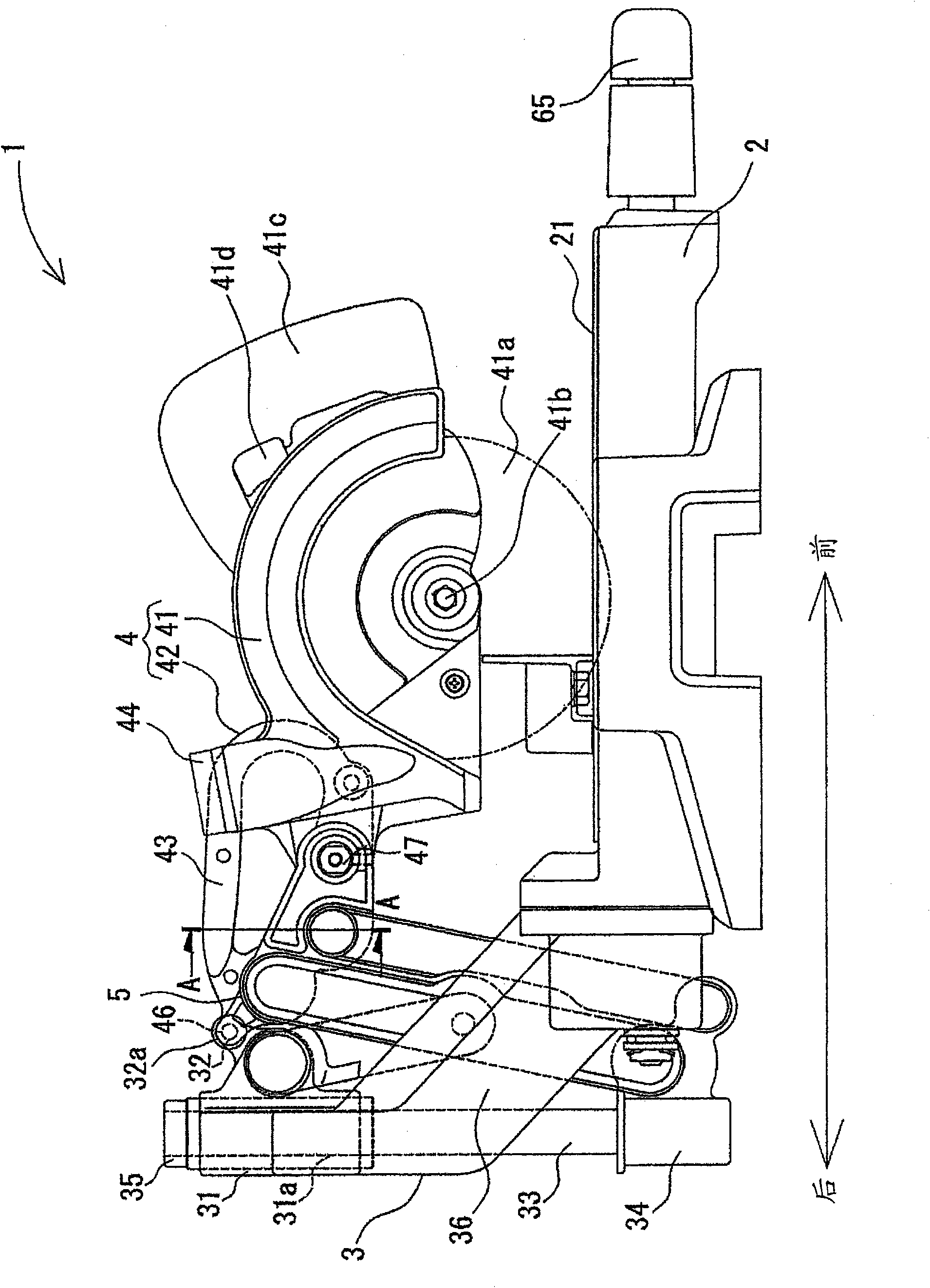
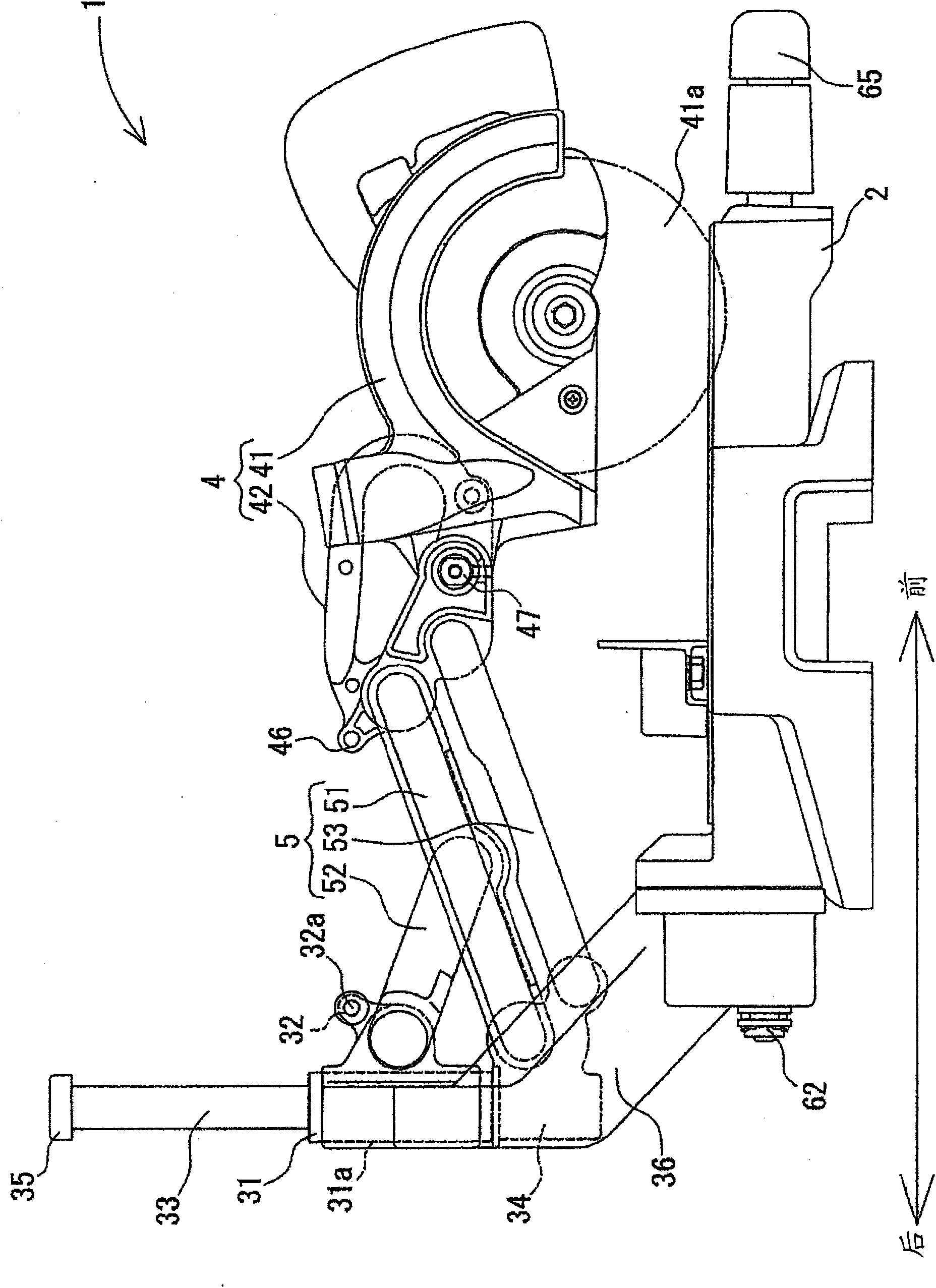
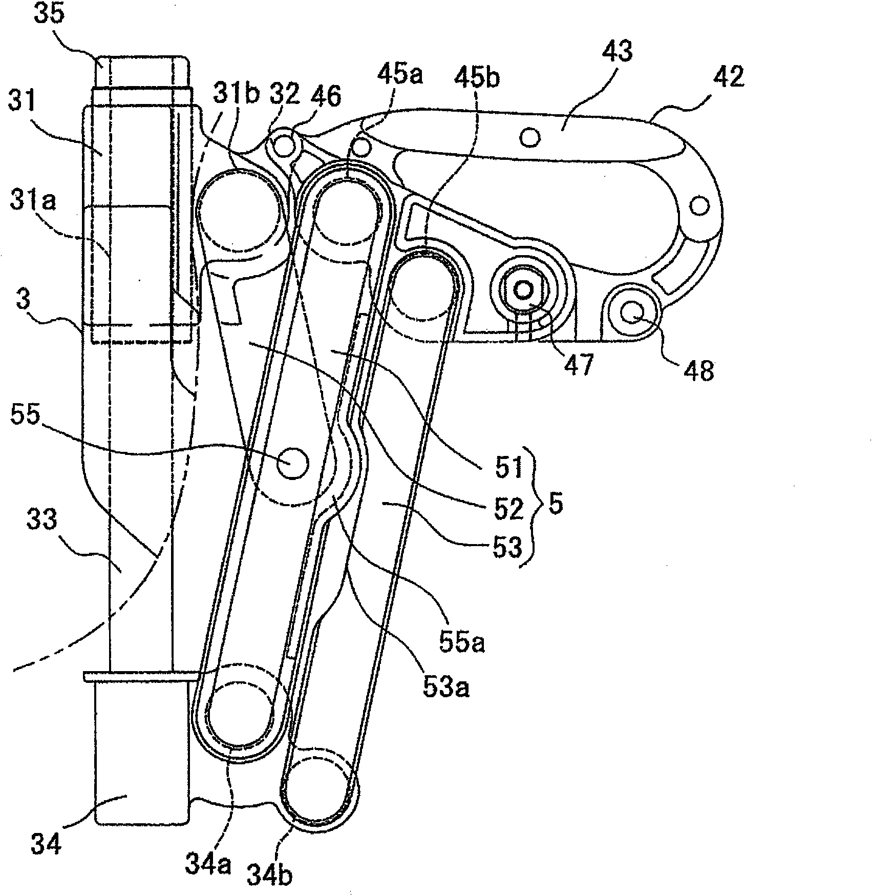
[0057] figure 1 It is a side view showing the overall structure of the sliding cutting machine according to this embodiment; figure 2 It is a side view showing the state where the cutting unit is moved to the operator's side; image 3 It is an enlarged view showing the coupling mechanism of the sliding cutter of this embodiment; Figure 4 It is a top view showing the overall structure of the sliding cutting machine according to this embodiment; Figure 5 It is a rear view showing the tilting movement mechanism of the linear guide device of the sliding cutting machine; Figure 6 yes figure 1 The A-A section diagram.

[0058] In addition...


PUM


Abstract

A slide type cutting machine which conducts cutting work of a timber etc. more safely and can be stored compactly. A straight guide device (3) has a slide shaft (33) which moves in a direction orthogonal to the moving direction of a cutting part (4), a first slide holder (31) which guides movement of the slide shaft (33), and a second slide holder (34) which is arranged at the lower end of the slide shaft (33) and abuts on the first slide holder (31) to control movement of the slide shaft (33). A linking means (5) has a first link (51) which has its one end connected with the cutting part (4) and the other end connected with the second slide holder (34), and a second link (52) which has its one end connected with the first slide holder (31) and the other end connected with the first link (51).

Description

technical field [0001] The present invention relates to a slide type cutting machine which moves a cutting part in a parallel and straight line relative to a base. Background technique [0002] Conventionally, there is known a cutting machine that cuts wood by rotating a blade such as a circular saw blade. Some of these cutting machines are equipped with a sliding mechanism for parallelly sliding a knife on a base on which wood or the like is placed, and can cut even long wood. [0003] Patent Document 1: (Japanese) Unexamined Patent Publication No. H11-156801 [0004] Patent Document 2: (Japanese) Unexamined Patent Publication No. 9-300301 [0005] Patent Document 3: (Japanese) Unexamined Patent Publication No. 7-276135 [0006] Patent Document 4: (Japanese) Unexamined Patent Publication No. 2006-198868 [0007] Patent Document 5: (Japanese) Unexamined Patent Publication No. 11-58302 [0008] The sliding cutting machine described in Patent Document 1 is provided with a...

Claims


Application Information

Patent Timeline
IPC IPC(8): B27B5/18B23D45/04
CPCB27B5/188Y10T83/7697Y10T83/7693Y10T83/7776Y10T83/8874
Inventor 大滨伸司
Owner RYOBI
Learn More