Photonic crystal optical fiber coupler for forming hollow light beam and preparation method thereof

A technology of photonic crystal fiber and hollow beam, which is applied in the coupling of optical waveguide, cladding optical fiber, optical waveguide light guide, etc., can solve the problems of multimode optical fiber length limitation, and achieve the effect of low cost, wide application range and easy realization

Inactive Publication Date: 2011-08-31
BEIJING JIAOTONG UNIV
View PDF1 Cites 0 Cited by
  • Summary
  • Abstract
  • Description
  • Claims
  • Application Information

AI Technical Summary

Problems solved by technology

China's patent application CN1834706A "Method for Generating Hollow Beam Using Interference Between Optical Fiber Modes and Tuning" discloses a method for generating hollow beams using intermode interference between optical fibers. This method requires support for LP 01 and LP 02 There are strict restrictions on the length of multimode fiber, and it is not easy to adjust parameters such as the beam width and width-to-radius ratio of the hollow beam

Method used


Image

  • Photonic crystal optical fiber coupler for forming hollow light beam and preparation method thereof
  • Photonic crystal optical fiber coupler for forming hollow light beam and preparation method thereof
  • Photonic crystal optical fiber coupler for forming hollow light beam and preparation method thereof

Examples


Embodiment 1

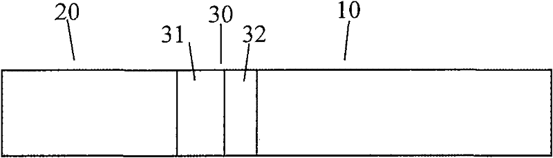
[0039] figure 1 A schematic diagram of a photonic crystal fiber coupler according to Embodiment 1 of the present invention is shown. The photonic crystal fiber coupler includes a ring-core photonic crystal fiber 10 , a single-mode fiber 20 and a fusion splicing region 30 with a fully collapsed region 31 and a gradually collapsed region 32 . figure 2 A schematic cross-sectional view of the ring-core photonic crystal fiber 10 in the photonic crystal fiber coupler in Embodiment 1 is shown. The diameter of the cladding of the ring-core photonic crystal fiber 10 is 125 μm, the background material 11 is pure quartz, the air holes 12 include air holes with a diameter of 1.2 μm arranged in a hexagon, and the distance between the centers of the holes is 2 μm, including the central air hole The number of air hole circles is 20 in total; the ring core 13 is made of pure quartz and has a hexagonal ring structure, and the distances from the center of the ring core photonic crystal fiber ...

Embodiment 2

[0044] Figure 5 A schematic diagram of a photonic crystal fiber coupler according to Embodiment 2 of the present invention is shown. The photonic crystal fiber coupler includes a ring-core photonic crystal fiber 10 , a single-mode fiber 20 and a fusion splicing region 30 with a fully collapsed region 31 and a gradually collapsed region 32 . Figure 6 A schematic cross-sectional view of the ring-core photonic crystal fiber 10 in the photonic crystal fiber coupler according to Embodiment 2 of the present invention is shown. The cladding diameter of the ring-core photonic crystal fiber 10 is 150 μm, the background material 11 is pure quartz, and the air holes 12 include large air holes with a diameter of 15 μm and small air holes with a diameter of 7.5 μm arranged at hexagonal intervals. The ring core 13 is made of fluorine-doped background material, its inner diameter is 7.5 μm, and its outer diameter is 37.95 μm. The thermal expansion coefficient of the ring core material is...


PUM


Abstract

The invention relates to a photonic crystal optical fiber coupler for forming hollow light beams and a preparation method thereof. The photonic crystal optical fiber coupler comprises a monomode optical fiber and a ring-core photonic crystal optical fiber, wherein one end of the monomode optical fiber is used as the input end of the photonic crystal optical fiber coupler; and one end of the ring-core photonic crystal optical fiber is used as the output end of the photonic crystal optical fiber coupler. The photonic crystal optical fiber coupler is characterized by further comprising a weldingjoint region of the other end of the ring-core photonic crystal optical fiber and the other end of the monomode optical fiber, so that the output end of the photonic crystal optical fiber coupler obtains the hollow light beams when the input end of the photonic crystal optical fiber coupler receives input light.

Description

technical field [0001] The invention relates to the field of optical fiber technology, in particular to a photonic crystal fiber coupler for forming a hollow beam and a preparation method thereof. technical background [0002] A hollow beam refers to a ring-shaped beam with low or zero center intensity in the propagation direction or axial direction of the beam. Different from Gaussian beams, hollow beams have many unique physical properties, such as cylindrical intensity distribution, small dark spot size, propagation invariance, and different optical angular momentums of different types of hollow beams, etc. The light intensity in the axial center of the hollow beam is zero, which can effectively reduce light scattering. The optical trapping efficiency of the hollow beam is higher than that of the Gaussian beam, and the optical damage to biological samples and particles is small. In addition, hollow beams can also be used to achieve optical rotation, light guidance, and e...

Claims


Application Information

Patent Timeline
Patent Type & Authority Patents(China)
IPC IPC(8): G02B27/09G02B6/26G02B6/02
Inventor 陈卫国娄淑琴盛新志王立文李宏雷苏伟
Owner BEIJING JIAOTONG UNIV
Why Eureka
Try Eureka