Eureka AIR delivers breakthrough ideas for toughest innovation challenges, trusted by R&D personnel around the world.

Full liquefying separation process for air-containing coal bed gas

A liquefaction separation and coal bed gas technology, applied in liquefaction, refrigeration, liquefaction, solidification, etc., can solve problems such as waste, complicated process flow, and failure to achieve complete separation of liquefied natural gas, and achieve the effect of reducing the number of equipment and simplifying process steps

Inactive Publication Date: 2010-09-01
CHINA UNIV OF PETROLEUM (BEIJING)
View PDF8 Cites 8 Cited by
  • Summary
  • Abstract
  • Description
  • Claims
  • Application Information

AI Technical Summary

Problems solved by technology

The separation of hydrocarbons, nitrogen and oxygen can be realized by two-stage rectification, but the two-stage rectification towers need to have independent reboilers and recondensers, and the equipment used is more, the process is more complicated, and the investment is higher. , although gas-liquid separation can be achieved and a certain amount of liquefied natural gas products can be obtained, but the complete separation of liquefied natural gas, liquid oxygen and liquid nitrogen cannot be achieved, and a part of the mixed gas in the middle is drawn out and released into the air, which will cause cause a certain waste
Although the single-stage rectification adopted in Chinese patent application No. 200610103425.0 has simplified equipment, it cannot realize the complete separation of natural gas, oxygen and nitrogen, and a part of the mixed gas in the middle is drawn out and released into the air, which will cause certain waste

Method used


Image

  • Full liquefying separation process for air-containing coal bed gas
  • Full liquefying separation process for air-containing coal bed gas
  • Full liquefying separation process for air-containing coal bed gas

Examples


Embodiment 1

[0051] This embodiment provides a fully liquefied separation process for air-containing coalbed methane. The hydrocarbon-oxygen separation equipment used in the process is a double-layer hydrocarbon-oxygen separation tower. The double-layer hydrocarbon-oxygen separation tower includes an upper tower and a lower tower, and , a condensing evaporator is arranged between the upper tower and the lower tower; the full liquefaction separation process comprises the following steps:

[0052] The compressed and purified air-containing coalbed methane is cooled and passed into the middle of the lower tower, through the heating at the bottom of the lower tower and the condensation on the condensation side of the condensing evaporator, liquid hydrocarbons are obtained at the bottom of the lower tower, and the mixed gas separated from the hydrocarbons is After throttling, it enters the top of the upper tower, or the mixed gas separated from hydrocarbons enters the middle of the nitrogen sepa...

Embodiment 2

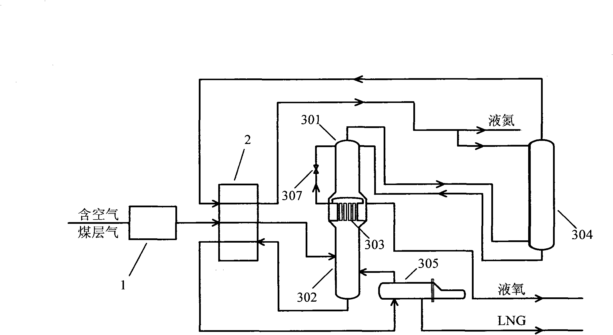
[0056] This embodiment provides a full liquefaction separation process for air-containing coalbed methane, wherein the full liquefaction separation equipment used is such as figure 1 shown.

[0057] The full liquefaction separation equipment includes a compression purification system 1, a cooling system 2 and a liquefaction separation system, wherein the compression purification system 1 is used to compress and purify the air-containing coalbed methane, and the cooling system 2 is used to provide refrigeration and can process part of the product The cold energy is recovered, both of which can adopt the system commonly used in this field;

[0058] The liquefaction separation system includes a double-layer hydrocarbon-oxygen separation tower and a nitrogen separation tower 304. The double-layer hydrocarbon-oxygen separation tower is composed of an upper tower 301 and a lower tower 302, and a condensation evaporator 303 is arranged between the upper tower 301 and the lower tower ...

Embodiment 3

[0067] This embodiment provides a full liquefaction separation process for air-containing coalbed methane, wherein the full liquefaction separation equipment used is such as figure 2 shown.

[0068] In this full liquefaction separation equipment, the cooling system includes a compressor 201, an air cooler 202, a gas-liquid separation tank 203, a compressor 204, an air cooler 205, a gas-liquid separation tank 206, a first Cold box 207 and second cold box 208, a section of gas-liquid separation tank 203 has an inlet, a top outlet and a bottom outlet, wherein:

[0069] One section of compressor 201, one section of air cooler 202, the inlet of one section of gas-liquid separation tank 203, the bottom outlet of one section of separation gas-liquid tank 203, the first cold box (second flow channel) 207, the first JT valve 209 and the first cooling Boxes (third runners) 207 are connected in sequence to form a high-temperature cycle;

[0070] One-stage compressor 201, one-stage air...


PUM


Abstract

The invention relates to a full liquefying separation process for an air-containing coal bed gas. In the process, equipment comprising a bilayer alkoxide separation tower and a nitrogen separation tower performs full liquefying separation on the air-containing coal bed gas, wherein the bilayer alkoxide separation tower comprises an upper tower and a lower tower; and a condensing evaporator is arranged between the upper tower and the lower tower. The process comprises the following steps of: introducing the air-containing coal bed gas into the lower tower after the coal bed gas is compressed and purified; condensing hydrocarbon into liquid to fall on the bottom of the lower tower through the heating of the bottom of the lower tower and condensation of the condensing evaporator to obtain liquefied natural gas; allowing the hydrocarbon-separated gas to rise to the top of the lower tower, to enter the top of the upper tower after throttling and to enter the nitrogen separation tower through the outlet on the top of the upper tower, or allowing the gas to enter the middle part of the nitrogen separation tower after throttling, wherein oxygen is condensed to liquefied oxygen on the top of the nitrogen separation tower, the liquefied oxygen returns to the bottom of the nitrogen separation tower, leaves from the outlet at the bottom of the nitrogen separation tower, returns to the top of the upper tower, and is output from the bottom of the upper tower; and outputting the nitrogen from the outlet of the top of the nitrogen separation tower, and cooling the nitrogen into liquefied nitrogen.

Description

technical field [0001] The invention relates to a gas liquefaction separation process, in particular to a full liquefaction separation process of air-containing coal bed gas. Background technique [0002] Coal bed methane, commonly known as gas, methane is adsorbed by coal during the formation of coal, that is, coal bed methane. my country's geological structure conditions are complex, and there are many high-gas mines and coal and gas outburst mines, accounting for 45% of the state-owned key coal mines alone. Gas is colorless, odorless, flammable and explosive, and will be separated and dispersed during the coal seam development process. When the gas concentration in the air is between 5.5% and 16% and there is an open flame, it is very easy to cause an explosion accident, which has become It has been a serious problem that has plagued coal mine safety production for a long time. More than 80% of the extraordinarily large and major accidents in my country's coal mines are c...

Claims


Application Information

Patent Timeline
IPC IPC(8): F25J3/00
Inventor 孙恒舒丹
Owner CHINA UNIV OF PETROLEUM (BEIJING)
Why Eureka
Eureka Blog
Learn More