Automatic control device of oil pipe clamping mechanism of non-well killing workover rig

A technology of automatic control device and clamping mechanism, which is applied to the automatic control system of drilling, wellbore/well components, oil traps, etc., which can solve the problems of no system safety guarantee, difficult pipeline layout, poor maintainability, etc., and achieve improved Safety, simple layout of network cables, and convenient maintenance

Active Publication Date: 2010-09-01
中石化四机石油机械有限公司 +1
View PDF4 Cites 8 Cited by
  • Summary
  • Abstract
  • Description
  • Claims
  • Application Information

AI Technical Summary

Problems solved by technology

Only adopting the hydraulic manual control method in the process of lifting (or pressing down) multiple oil pipes has the following defects: the realization of each step requires the sequential operation of multiple hydraulic operating handles, so realizing each snubbing workover operation requires each A hydraulic operating handle is operated repeatedly and sequentially for many times, which may easily cause misoperation; the number of liquid and gas pipelines connecting the operating handle on the second-floor driller's floor with the actuator valve on the platform is more than 20, and the layout of the pipelines Difficult, poor maintainability; no system security guarantee, operators cannot predict and judge some failure safety hazards

Method used


Image

  • Automatic control device of oil pipe clamping mechanism of non-well killing workover rig
  • Automatic control device of oil pipe clamping mechanism of non-well killing workover rig
  • Automatic control device of oil pipe clamping mechanism of non-well killing workover rig

Examples


Embodiment Construction

[0014] The present invention is illustrated below by an example.

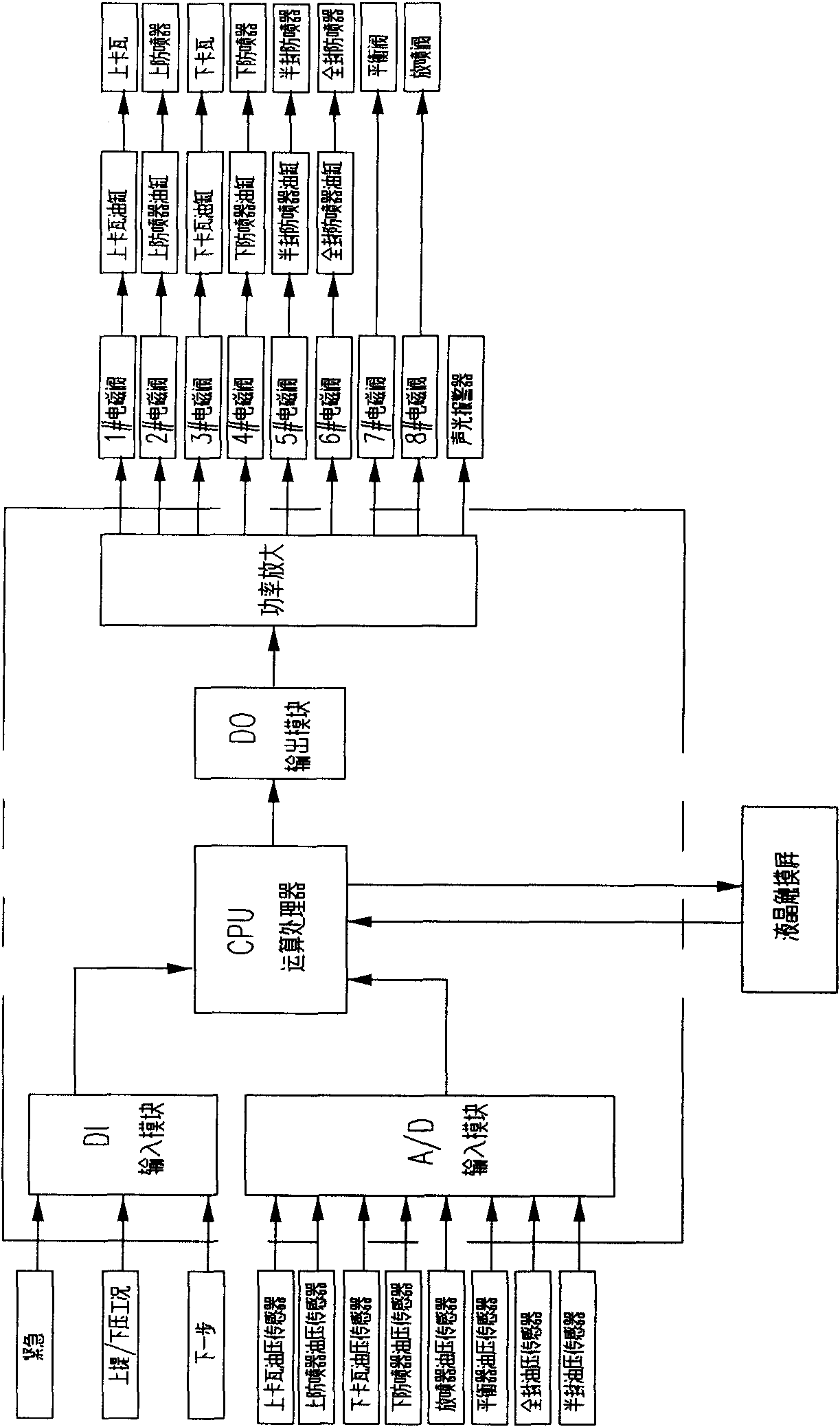
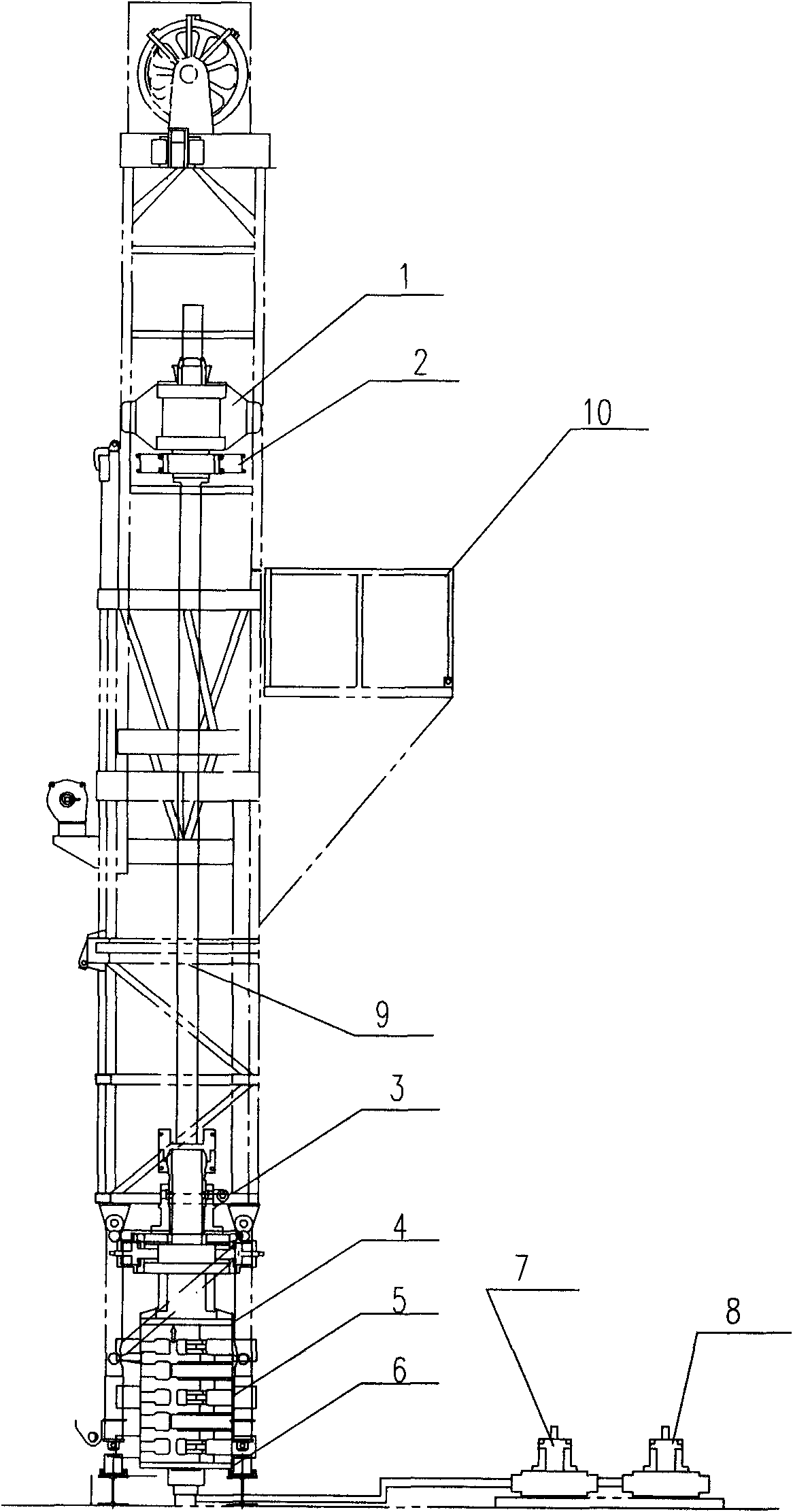
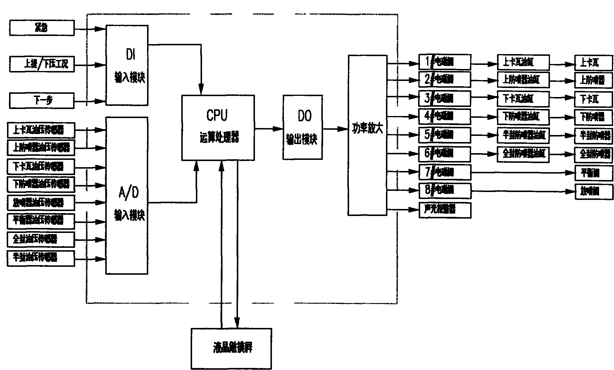
[0015] see figure 1 , figure 2 , during the snubbing workover operation, a tubing clamping mechanism is set in the movement path of the tubing 9 so that the tubing 9 can be clamped in an orderly manner. The tubing clamping mechanism consists of the upper slip 1 and the upper blowout preventer 2 , lower slip 3, lower blowout preventer 4, semi-sealed blowout preventer 5, full-seal blowout preventer 6, balanced shut-off valve 7, blowout shut-off valve 8, etc. The above-mentioned device is connected with the corresponding hydraulic control cylinder through the cam mechanism, and is connected with the eight solenoid valves installed on the platform one by one. At the same time, eight oil pressure sensors are installed one by one on the hydraulic inlet pipe of the above-mentioned oil cylinder and valve On the road, three operating switches of "uplift / down", "next step" and "emergency stop" are installed on the ope...


PUM


Abstract

The invention relates to an automatic control device of an oil pipe clamping mechanism of a non-well killing workover rig, belonging to the field of non-well killing workover operation equipment. The automatic control device is used for the non-well killing workover operation equipment and comprises a control device, a plurality of electromagnetic valves, oil pressure sensors and hydraulic oil cylinders, wherein the control device takes a controller loading self-authoring software as a core; the oil pressure sensors are the same as the electromagnetic valves in number; and the hydraulic oil cylinders are the same as the electromagnetic valves in number. The automatic control device is characterized in that a data processing device comprises a DI (Data Input) module, a CPU operation processor, a DO (Data Output) module, a power amplifier, an A / D (Analog / Digital) input modules and a CPU, wherein the DI module, the CPU operation processor, the DO module and the power amplifier are sequentially connected, and the A / D input module is connected with the CPU; an executive device comprises eight electromagnetic valves, six hydraulic oil cylinders, two hydraulic valves and a clamping mechanism; and the input end of the A / D input module is also connected with eight oil pressure sensors, and the oil pressure sensors are connected with oil inlet pipelines of the hydraulic oil cylinders orthe hydraulic valves one by one. The invention solves the problem of equipment safety caused by the complexity and the easy error of the manual operation of the oil pipe clamping mechanism and reduces the labor intensity of operators.

Description

Technical field: [0001] The invention relates to an automatic control device for an oil pipe clamping mechanism of a snubbing workover operation equipment in an oil and gas field. Background technique: [0002] The so-called no-snubbing operation is an advanced operation technology in which oil wells do not need to be killed by mud, and water wells are not blown out, but under the control of the self-sealing blowout preventer at the wellhead. The snubbing workover rig is mainly composed of chassis, engine, gearbox, hydraulic system, pneumatic system, tubing clamping mechanism and other components. Among them, the oil pipe clamping mechanism is mainly composed of 8 devices: upper slip, upper blowout preventer, lower slip, lower blowout preventer, balance cut-off valve, discharge cut-off valve, full-sealing blowout preventer, and half-sealing blowout preventer Through the sequential actions of the above devices, the clamping of the oil pipe in the process of lifting and press...

Claims


Application Information

Patent Timeline
Patent Type & Authority Applications(China)
IPC IPC(8): E21B44/00E21B40/00
Inventor 池胜高孟庆珍曹立明杨德强刘洪亮李勇
Owner 中石化四机石油机械有限公司
Why Eureka
Try Eureka