
Method for exploiting natural gas hydrates by using high-pressure thermal jetting

A natural gas and hydrate technology, which is applied in the direction of production fluid, earthwork drilling, wellbore/well components, etc., can solve the problems of large heat loss, small mining range, and little contribution to the decomposition of natural gas hydrate, so as to ensure cutting, Good heat conduction effect, overcome self-protection effect

Inactive Publication Date: 2010-09-01
JILIN UNIV
View PDF6 Cites 28 Cited by
  • Summary
  • Abstract
  • Description
  • Claims
  • Application Information

AI Technical Summary

Problems solved by technology

According to the article "Natural Gas Hydrate Exploitation-Taking Malik Drilling as an Example" written by Luan Xiwu and others, the Malik gas field in Canada has been successfully exploited by the thermal stimulation method, but the thermal stimulation method mainly uses heat conduction to decompose natural gas hydrate. The mining area is small, and thermal convection does not make much contribution to the decomposition of natural gas hydrate due to the limitation of contact area, and its heat loss is too large; This paper introduces the situation of mining hydrates by depressurization method in Russia. This method has achieved good mining results, but the depressurization method can only be used effectively when there are natural gas fields in the lower part of the gas hydrate deposit. The application of the method is limited by the occurrence conditions of natural gas hydrate

Method used


Image

  • Method for exploiting natural gas hydrates by using high-pressure thermal jetting
  • Method for exploiting natural gas hydrates by using high-pressure thermal jetting

Examples


Embodiment 1

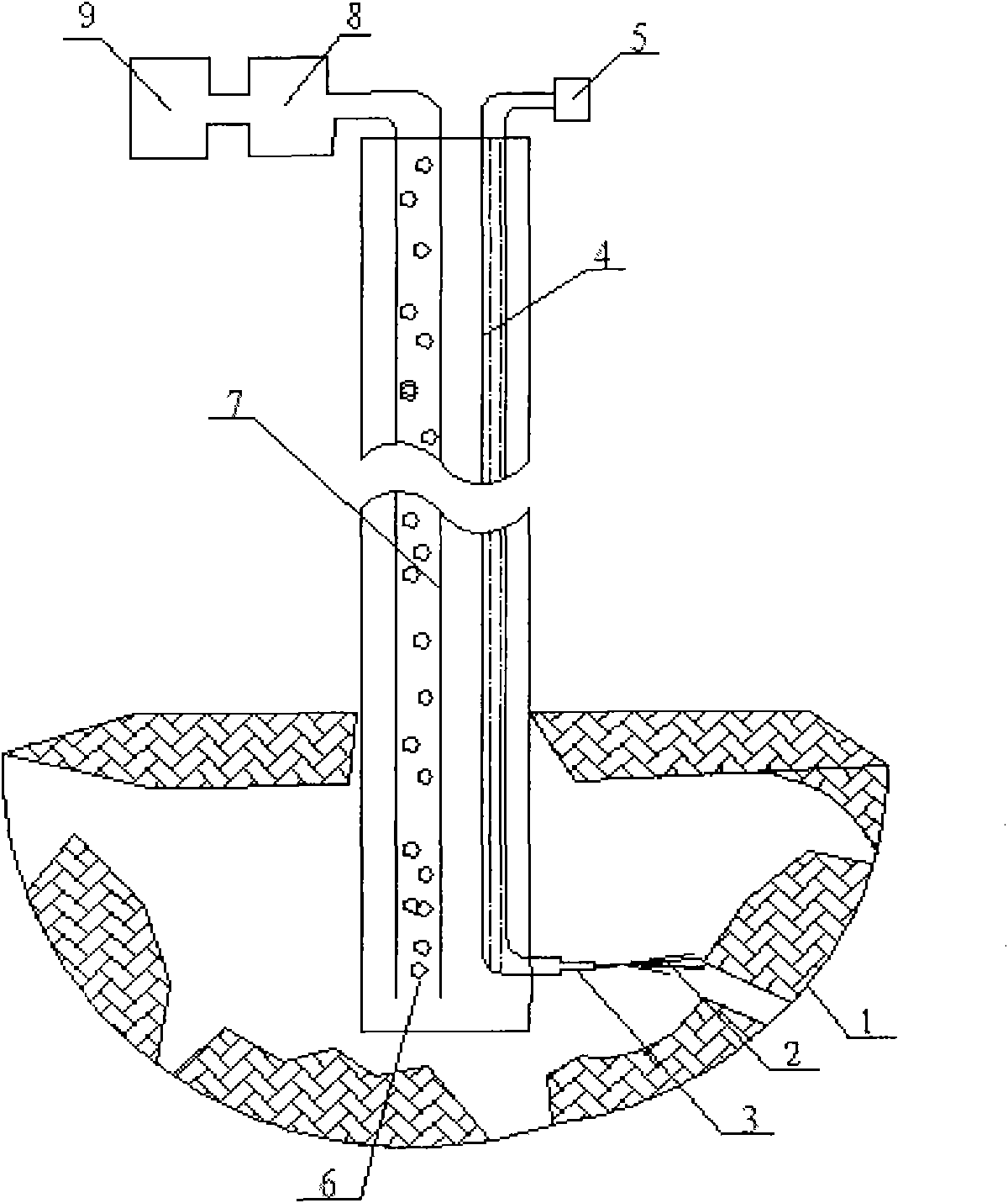
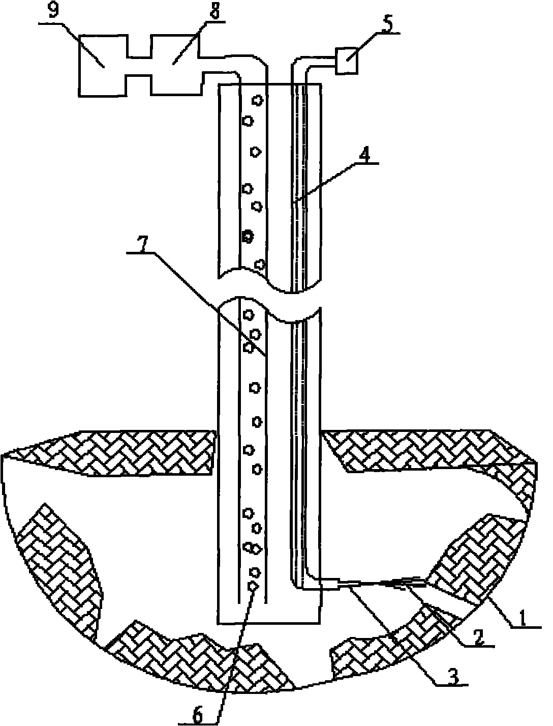
[0021] a. Using a core drilling rig to drill a production well on the geological body where the natural gas hydrate is pre-exploited;

[0022] b. Send the water injection pipe 4 and the telescopic water gun 3 into the production well together with the production pipe 7 after threaded connection;

[0023] c. The exploitation pipe 7 is connected with the gas-liquid separation device 8 through threads, and the gas-liquid separation device 8 is connected with the gas recovery device 9 through threads;

[0024] d. The hot fluid 2 with a pressure of 10MPa, a flow velocity of 300m / s, and a temperature of 80°C is sent through the high-pressure pump 5 into the water injection pipe 4 and the retractable water gun 3 to generate a high-speed jet to act on the natural gas hydrate 1;

[0025] e. The high-speed jet directly acts on the natural gas hydrate 1 within its working radius, so that the natural gas hydrate 1 is cut and decomposed, and the undecomposed natural gas hydrate, natural ga...

Embodiment 2

[0030] a. Using a core drilling rig to drill a production well on the geological body where the natural gas hydrate is pre-exploited;

[0031] b. Send the water injection pipe 4 and the telescopic water gun 3 into the production well together with the production pipe 7 after threaded connection;

[0032] c. The exploitation pipe 7 is connected with the gas-liquid separation device 8 through threads, and the gas-liquid separation device 8 is connected with the gas recovery device 9 through threads;

[0033] d. The hot fluid 2 with a pressure of 20MPa, a flow velocity of 300m / s, and a temperature of 65°C is sent through the high-pressure pump 5 into the water injection pipe 4 and the retractable water gun 3 to generate a high-speed jet to act on the natural gas hydrate 1;

[0034] e. The high-speed jet directly acts on the natural gas hydrate 1 within its working radius, so that the natural gas hydrate 1 is cut and decomposed, and the undecomposed natural gas hydrate, natural ga...

Embodiment 3

[0037] a. Using a core drilling rig to drill a production well on the geological body where the natural gas hydrate is pre-exploited;

[0038] b. Send the water injection pipe 4 and the telescopic water gun 3 into the production well together with the production pipe 7 after threaded connection;

[0039] c. The exploitation pipe 7 is connected with the gas-liquid separation device 8 through threads, and the gas-liquid separation device 8 is connected with the gas recovery device 9 through threads;

[0040] d. Send the thermal fluid 2 with a pressure of 30MPa, a flow velocity of 300m / s, and a temperature of 50°C through the high-pressure pump 5 into the water injection pipe 4 and the retractable water gun 3 to generate a high-speed jet to act on the natural gas hydrate 1;

[0041] e. The high-speed jet directly acts on the natural gas hydrate 1 within its working radius, so that the natural gas hydrate 1 is cut and decomposed, and the undecomposed natural gas hydrate, natural g...


PUM


Abstract

The invention relates to a method for exploiting natural gas hydrates by using high-pressure thermal jetting, comprising the following steps of: placing a high-pressure jetting device in an exploiting well; sending thermal fluids into a water injection pipe and a telescopic water gun through a high-pressure pump for spraying; causing high-speed jetting flows to directly act on the natural gas hydrates in the working radii of the high-speed jetting flows to cut and decompose the natural gas hydrates, changing non-decomposed natural gas hydrates into small blocks, bringing the small blocks into an exploiting pipe along with return flows, and then causing the small blocks together with the gas hydrates to rise to a gas-liquid separation device; separating gas and liquid through the gas-liquid separation device, and sending the gas into a gas recovering device. The invention solves the problem of small exploitation range in the exploitation process of the natural gas hydrates, ensures the thermal fluids to act on the surfaces of the non-cracked natural gas hydrates all the time, has a good thermal conduction effect and overcomes or reduces the self protection of the natural gas hydrates; and the telescopic water gun on a nozzle can not only be horizontally rotated, but also can be moved up and down along a vertical shaft by utilizing the power of a drilling machine, thereby ensuring the cutting of large-scale natural gas hydrate ledges.

Description

Technical field: [0001] The invention relates to a method for exploiting natural gas hydrate, in particular to a method for exploiting natural gas hydrate by using high-pressure hot jet flow. Background technique: [0002] Existing natural gas hydrate mining methods include thermal excitation method, depressurization method, and chemical reagent injection method. The mining mechanism of the above methods is to break the conditions for the stable existence of hydrates, promote their decomposition, and achieve the purpose of mining. According to the article "Natural Gas Hydrate Exploitation - Taking Malik Drilling as an Example" written by Luan Xiwu and others, the thermal stimulation method was successfully used in the Malik gas field in Canada, but the thermal stimulation method mainly uses heat conduction to decompose gas hydrate The mining area is small, and thermal convection does not contribute much to the decomposition of natural gas hydrate due to the limitation of the...

Claims


Application Information

Patent Timeline
IPC IPC(8): E21B43/24
Inventor 陈晨孙友宏房治强高文爽陈大勇冯雪威
Owner JILIN UNIV
Learn More