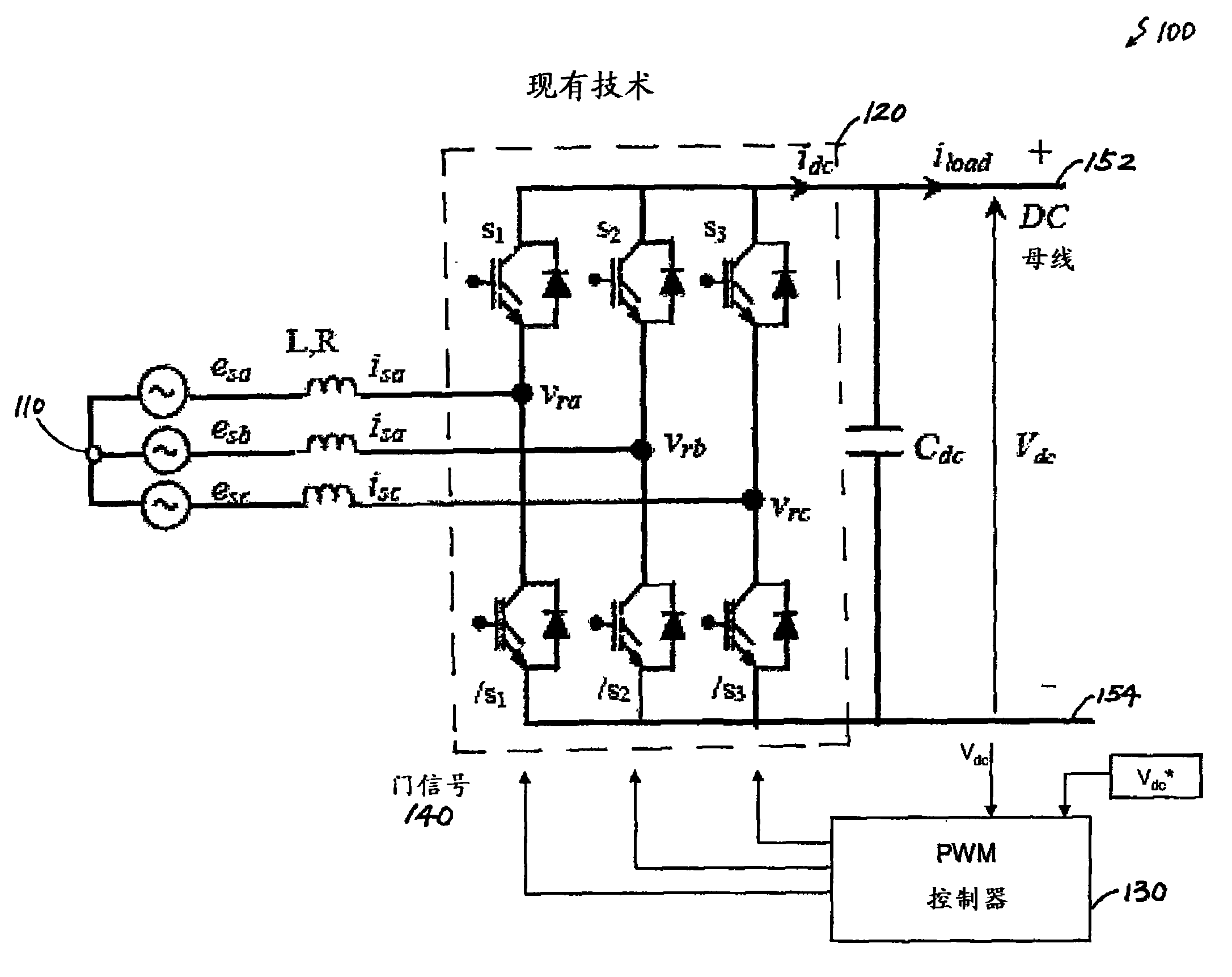
DC bus voltage harmonics reduction
A voltage and DC link technology, applied in the direction of converting AC power input to DC power output, electrical components, high-efficiency power electronic conversion, etc., can solve problems such as deteriorating DC power quality, system tripping, etc., to minimize cost and eliminate input current. Distortion and voltage fluctuation, the effect of improving stability
Inactive Publication Date: 2010-08-25
AMERICAN SUPERCONDUCTOR
View PDF1 Cites 7 Cited by
- Summary
- Abstract
- Description
- Claims
- Application Information
AI Technical Summary
Problems solved by technology
Negative sequence components cause even harmonics in the DC link voltage and odd harmonics in the converter current, which can significantly deteriorate the quality of the DC power supplied to the load
In extreme conditions, this may even cause the system to trip if the maximum DC bus voltage is exceeded
In large power conversion systems, these problems can become worse as the number of converters connected to a common AC chain increases
Method used
View moreImage
Smart ImageViewing Examples
Examples
Embodiment Construction
Login to View More PUM
 Abstract
In one aspect, in general, the invention features a control system configured for use with a three-phase PWM converter. The control system receives an input signal from a three-phase power supply and provides an output signal at a DC link. A voltage-separating module generates on the basis of the input signal a positive sequence voltage component and a negative sequence voltage component in a rotating reference frame. A reference current computation module uses at least the positive sequence voltage component and the negative sequence voltage component to compute a first reference current and a second reference current. A current regulating module uses at least the first reference current and the second reference current to generate a command signal. The command signal is provided to a driving circuit of the three-phase PWM converter for generating a regulated DC bus voltage at the DC link.
Description
Cross References to Related Applications This application claims the benefit of US Application Serial No. 12 / 057,856, filed March 28, 2008, the contents of which are hereby incorporated in their entirety. Background technique The present invention relates to a power conversion system for generating a regulated direct current (DC) bus voltage from an alternating current (AC) power source. Electricity generated by the power plant is transmitted to consumers through the utility grid in the form of three-phase AC power. However, AC power is not always suitable for an end use and sometimes needs to be converted to a usable form (eg, DC) before being connected to a load. In this case, use an AC / DC converter. Generally, an AC / DC converter receives alternating current at its input and outputs direct current at its DC link. To produce a satisfactory output, the AC / DC converter is often operated with a controller that regulates the shape and amplitude of the DC bus voltage to a de...
Claims
Login to View More Application Information
Patent Timeline
 Patent Type & Authority Applications(China)
IPC IPC(8): H02M7/162H02M1/42
CPCY02B70/126H02M7/217H02M1/4216Y02B70/10
Inventor 刘彦真
Owner AMERICAN SUPERCONDUCTOR
- R&D Engineer
- R&D Manager
- IP Professional
- Industry Leading Data Capabilities
- Powerful AI technology
- Patent DNA Extraction
Learn More Browse by: Latest US Patents, China's latest patents, Technical Efficacy Thesaurus, Application Domain, Technology Topic, Popular Technical Reports.
© 2024 PatSnap. All rights reserved.Legal|Privacy policy|Modern Slavery Act Transparency Statement|Sitemap|About US| Contact US: help@patsnap.com


