Multi-antenna transmit diversity method and device
A transmit diversity, multi-antenna technology, applied in space transmit diversity, diversity/multi-antenna systems, and error prevention/detection through diversity reception, can solve the problem of not providing a multi-antenna transmit diversity scheme, and achieve good diversity gain. Effect
Inactive Publication Date: 2010-08-25
ZTE CORP
View PDF4 Cites 20 Cited by
- Summary
- Abstract
- Description
- Claims
- Application Information
AI Technical Summary
Problems solved by technology
In view of this, the main purpose of the present invention is to provide a multi-antenna transmit diversity method and device to solve the problem that the current related art does not provide a multi-antenna transmit diversity scheme
Method used
View moreImage
Smart ImageViewing Examples


Examples
example 1
example 2
Login to View More PUM
 Abstract
The invention discloses a multi-antenna transmit diversity method and a device. In the scheme of the invention, the method comprises the following steps: setting a coding matrix of wave beam groups and frequencies; dividing wave beams generated by a plurality of antennas into two misaligned groups to obtain two wave beam groups; and determining signs sent by the wave beam groups at different frequencies according to the coding matrix. The invention provides a multi-antenna transmit diversity scheme, and solves the problem that the current relevant technology does not provide the multi-antenna transmit diversity scheme, in addition, good diversity grain can be obtained at the same time of not increasing the additional pilot frequency overhead. The invention has the technical scheme that the multi-antenna transmit diversity is combined with the wave beam formation in a multi-antenna communication system, different signs correspond to different wave beam groups, and further, the state switching of the wave beam group is carried out. Thereby, compared with the traditional two-antenna space-frequency coding, the diversity scheme of the invention has the performance grain of 6dB, and in addition, the signs can be completely covered in the state switching of the wave beam groups.
Description
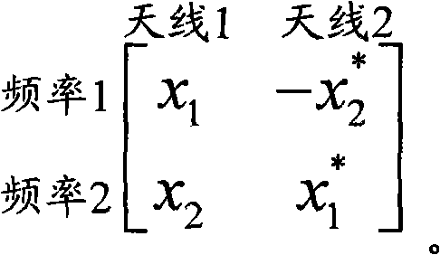
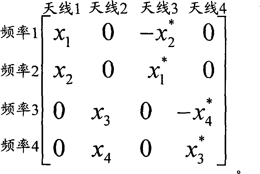
technical field The invention relates to the field of wireless communication, in particular to a multi-antenna transmit diversity method and device. Background technique In the 3rd Generation Partnership Project (3GPP, 3rd Generation Partnership Project) Long-Term Evolution (LTE, Long-Term Evolution) system, the downlink defines that the diversity mode when the transmit antenna is 2 antennas is Space Frequency Block Coding (SFBC, Space Frequency Block Codes,), the encoding matrix is: wherein, each row of the encoding matrix corresponds to a different frequency, and each column corresponds to a different antenna, x 1 、x 2 is the symbol before space-frequency coding, x * Indicates the conjugate of x. The downlink also defines the diversity mode when there are 4 antennas as frequency switching diversity (SFBC+FSTD, SFBC+Frequency Switch Time Division), and the encoding matrix is: where each row of the encoding matrix corresponds to a different frequency, and each column cor...
Claims
Login to View More Application Information
Patent Timeline
 IPC IPC(8): H04B7/06H04B7/08H04L1/06
Inventor 王衍文李岩谭欢喜
Owner ZTE CORP
Features
- R&D
- Intellectual Property
- Life Sciences
- Materials
- Tech Scout
- Unparalleled Data Quality
- Higher Quality Content
- 60% Fewer Hallucinations
Learn More Browse by: Latest US Patents, China's latest patents, Technical Efficacy Thesaurus, Application Domain, Technology Topic, Popular Technical Reports.
© 2025 PatSnap. All rights reserved.Legal|Privacy policy|Modern Slavery Act Transparency Statement|Sitemap|About US| Contact US: help@patsnap.com