
Vehicle-mounted eddy strong pulse resonant jet cleaning device

A technology of powerful pulse and cleaning device, applied in the direction of spray device, spray device, cleaning method and utensils, etc., can solve the problems of unsuitable field and mobile operation, unfavorable promotion and use, inconvenient operation, etc., to improve mobility and field operation. Ability to work, reduce manufacturing costs and O&M costs, enhance the effect of erosion and crushing

Inactive Publication Date: 2010-08-25
任保林
View PDF0 Cites 23 Cited by
  • Summary
  • Abstract
  • Description
  • Claims
  • Application Information

AI Technical Summary

Problems solved by technology

Continuous flow water jet equipment must be robustly designed to withstand the extremely high water pressure required, so the nozzles, water piping and fittings are bulky, heavy and expensive; in order to provide ultra-high pressure water jets, expensive ultra-high pressure water pumps are required, which The manufacturing cost and operating cost of this ultra-high pressure pump and equipment are very high, and there are disadvantages such as low efficiency and high energy consumption.
On the other hand, most of the existing high-pressure water jet cleaning devices are fixed and inconvenient to operate, and cannot be applied to field and mobile operations, which is not conducive to the promotion and use of large areas.

Method used


Image

  • Vehicle-mounted eddy strong pulse resonant jet cleaning device
  • Vehicle-mounted eddy strong pulse resonant jet cleaning device
  • Vehicle-mounted eddy strong pulse resonant jet cleaning device

Examples


Embodiment Construction

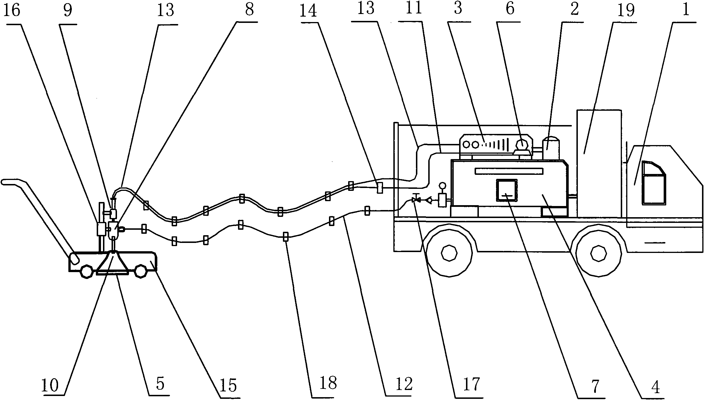
[0021] As shown in Figure 1 and Figure 2, the vehicle-mounted eddy current strong pulse resonance jet cleaning device described in the embodiment of the present invention includes a carrier vehicle 1, a power supply 2, an electrical control device 7, an ultrasonic generating device 3, an air cooling device 6, a high-pressure The water jet generating device 4 and the nozzle device, the nozzle device includes an ultrasonic transducer vibrator 9, a horn 10, a powerful pulse oscillation chamber 8 and a vortex resonance jet nozzle 5; the ultrasonic transducer vibrator 9 passes through the ultrasonic generator 3 The ultrasonic transmission cable 13 is connected to the air cooling device 6 through a cooling compressed air pipe 11 ; the powerful pulse oscillation chamber 8 is connected to the high-pressure water jet generator 4 through a high-pressure water inlet pipeline 12 .

[0022] Water tank 19, electrical control device 7, ultrasonic generator 3, high-pressure water jet generator...


PUM


Abstract

The invention discloses a vehicle-mounted eddy strong pulse resonant jet cleaning device comprising a carrying vehicle 1, a power supply 2, an electrical control device 7, an ultrasonic generating device 3, an air cooling device 6, a high-pressure water jet generating device 4 and a spray head device, wherein the spray head device comprises an ultrasonic transduction vibrator 9, an amplitude transformer 10, a strong pulse vibrating chamber 8 and an eddy resonant jet spray head 5; the ultrasonic transduction vibrator 9 is connected with the ultrasonic generating device 3 by an ultrasonic transmission cable 13 and is connected with the air cooling device 6 by a cooling compressed air tube 11; and the strong pulse vibrating chamber 8 is connected with the high-pressure water jet generating device 4 by a high-pressure water inlet pipeline 12. In the invention, the energy of high-pressure water jet and eddy resonance and the energy of strong high-frequency mechanical vibration pulses generated by the ultrasonic generator are sufficiently utilized to form a stable eddy strong pulse resonant jet in the vibration chamber, which obviously improves the energy efficiency of the jet and reinforces the washing action and the crushing action generated on the surface of a material by the pulse jet; and the complete set of device does not need to be configured with additional power supply and cooling air source by customers. The cleaning device has a style of the own, convenient operation and better cleaning effect and is especially suitable for field work and maneuvering work.

Description

technical field [0001] The invention relates to a high-pressure water jet cleaning device, in particular to a vehicle-mounted high-pressure water jet cleaning device capable of generating pulse jets. Background technique [0002] High-pressure water jet technology and equipment are widely used in industrial cleaning, cutting, deburring and surface coating peeling. According to the specific application, it can be divided into continuous pure water jet, abrasive water jet and so on. In general industrial cleaning, most of them use continuous pure water jets. In the field of rust removal and paint removal, the pressure of high-pressure water required is generally 150-250Mpa, while in the removal of some hard metal coatings and deburring, continuous pure water up to 350-420Mpa is required. high-pressure jet to complete. Continuous flow water jet equipment must be robustly designed to withstand the extremely high water pressure required, so the nozzles, water piping and fittin...

Claims


Application Information

Patent Timeline
Patent Type & Authority Applications(China)
IPC IPC(8): B08B3/02B05B1/34B26F3/00B02C19/06
Inventor 任保林叶乔任吉林
Owner 任保林
Learn More