
Fluidized bed reactor

A fluidized bed reactor and reactor technology, applied in the direction of chemical instruments and methods, chemical/physical processes, etc., can solve the problems of increased external circulation compressor power, reduced reactor production capacity, and small catalyst loading coefficient, etc. Achieve the effects of bed temperature balance, bed pressure reduction, and a wide range of uses

Inactive Publication Date: 2010-08-18
ENN XINNENG BEIJING TECH
View PDF5 Cites 24 Cited by
  • Summary
  • Abstract
  • Description
  • Claims
  • Application Information

AI Technical Summary

Problems solved by technology

Adiabatic fixed-bed reactors (US4,064,256, US4,298,694 and US4,130,573) have no heat exchange equipment in the catalyst layer, and use a large amount of product gas to circulate to control the temperature of the catalyst bed. The structure is relatively simple, the space utilization rate is high, and the cost is low, but If the heat of reaction cannot be removed in time, for the exothermic reversible reaction, due to the excessive temperature rise, the axial temperature distribution of the reactor will be far from the optimal temperature distribution, resulting in a decrease in the production capacity of the reactor, or even due to the limitation of chemical equilibrium. The outlet of the reactor cannot reach the required conversion rate, and it will impose a burden on the material selection and cost of the equipment. Even if the operating temperature of the reactor is lowered, the excessive product gas circulation will directly increase the linear velocity of the reaction gas and the catalyst bed. height, resulting in excessive pressure drop in the reactor and an increase in the power of the external cycle compressor
The heat exchange fixed bed reactor (ZL00208802.9 and CN87102871) adopts the catalyst inside the tube and the heat transfer medium outside the tube. This reactor has the advantages of small bed temperature difference, stable operation and convenient adjustment, but the catalyst loading coefficient is small, High gas flow resistance

Method used


Image

  • Fluidized bed reactor
  • Fluidized bed reactor
  • Fluidized bed reactor

Examples


Embodiment Construction

[0037] The present invention will be described in detail below in conjunction with the accompanying drawings. The following are only preferred embodiments of the present invention, and the scope of the present invention cannot be limited thereto. That is, all equivalent changes and modifications made according to the scope of the patent application of the present invention should still fall within the scope covered by the patent of the present invention.

[0038] The present invention will be further described below in conjunction with accompanying drawing.

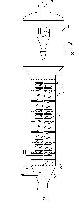
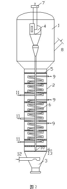
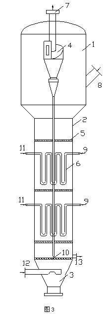
[0039] Such as figure 1As shown, the present invention comprises: the expansion tube 1 at the upper end of the reactor, the straight tube 2 in the middle of the reactor, the cone bottom 3 at the bottom of the reactor, the cyclone separator 4, the internal components 5, the heat exchange device 6, the product gas outlet 7 at the top of the shell , Catalyst filling port 8 on the expansion tube, heat transfer medium outlet ...


PUM

PropertyMeasurementUnit
Particle sizeaaaaaaaaaa

Abstract

The invention provides a fluidized bed reactor. A fine particle catalyst makes a suspension motion under the effect of the ascending reaction gas air steam, the solid particles flip up and down dramatically to fully mixing the reaction gas air together with the particles in a bed layer and avoid the 'hot spot' in a stationary bed reactor, the temperature distribution inside the bed layer is uniform, a laminar boundary layer nearby a heat transfer surface is damaged to improve the heat transfer coefficient, large amount of heat generated by catalytic reactions such as methane synthesis is removed through a raw gas in a heat exchange tube so as to reduce the temperature of a catalyst bed layer, make the temperature distribution of the bed layer more uniform, improve the conversion rate of the raw gas, and enhance the production capability of the reactor. The reactor has the advantages of reasonable structure, uniform bed layer temperature, reduced bed layer pressure, high efficiency for heat transfer and mass transfer and strong reaction capability.

Description

technical field [0001] The invention relates to the field of catalytic reaction, in particular to a reactor for catalytic process. Background technique [0002] Fluidized bed reactor is a type of reactor widely used in chemical process, especially suitable for systems with significant exothermic effect or strict temperature control requirements. Such as catalytic cracking reaction, ethylene oxychlorination, butene oxidative dehydrogenation, acrylonitrile synthesis, methane synthesis and other reactions. The important feature of the fluidized bed reactor is that the fine-grained catalyst is suspended under the action of the updraft, and the solid particles are violently turned up and down. This form of movement makes the fluid and particles in the bed fully agitated and mixed, avoiding the "hot spot" phenomenon in the fixed bed reactor, the temperature distribution in the bed is uniform, the entire reaction system is in an isothermal environment, and the heat transfer surfac...

Claims


Application Information

Patent Timeline
IPC IPC(8): B01J8/24
Inventor 次东辉李欢蒋建明田文堂郭迎秋
Owner ENN XINNENG BEIJING TECH
Learn More