Myoelectric Knee
A knee joint and myoelectric technology, applied in the field of myoelectric knee joints, can solve the problems of no stretching, no support, etc., and achieve the effect of smooth oil passage
- Summary
- Abstract
- Description
- Claims
- Application Information
AI Technical Summary
Problems solved by technology
Method used
Image
Examples
Embodiment 1
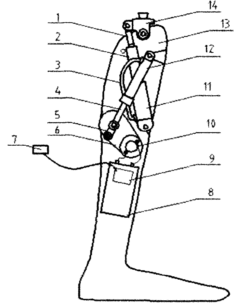
[0022] When the disabled person equipped with this prosthetic was walking on a flat road, the sensor (myoelectric sensor) 7 sent a signal A to the control module 9, and after the discrimination of the program in the control module, the control system controlled the motor not to run. The joint starts the hydraulic mechanical operation mode on the ground, and the joint operation is driven by the strength of the residual limbs of the human body and the oil circuit control maintains the stability of the joint to achieve the purpose of saving electricity.
[0023] At this moment, the speed reducer can be passively rotated under the condition that the motor is not working, so as not to prevent the rotation of the joint.
Embodiment 2
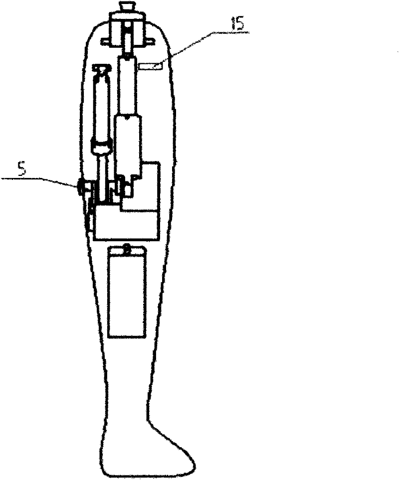
[0025] When the disabled need to go up the stairs, the sensor (myoelectric sensor) 7 will send a signal B to the control module 9, and through the discrimination of the program in the control module 9, the operation of the motor 10 will be controlled, and the rotary motion will be decelerated by the reducer 6 Transferred to the crank 5, the rotational movement of the crank 5 will drive the small hydraulic cylinder piston rod 4 and the small hydraulic cylinder body 12 to move relative to each other, and the small hydraulic cylinder is connected to the large hydraulic cylinder through the oil pipe 3, so it will push the second stage of the large hydraulic cylinder When the piston rod moves, due to the different cross-sectional areas, there will be a force-increasing effect. Since the cavity of the second-stage piston rod of the large hydraulic cylinder is sealed, the relative stroke between the first-stage piston rod 1 of the large hydraulic cylinder and the second-stage piston r...
Embodiment 3
[0027] When the disabled need to squat down, the sensor (myoelectric sensor) 7 sends a signal C to the control module 9, the control module 9 controls the motor will not be started, and the secondary piston rod 2 of the large hydraulic cylinder will not contact with the cylinder body of the large hydraulic cylinder 11 produces relative motion. The rotary motion of the joint head 14 will compress the first-stage piston rod 1 of the large hydraulic cylinder. When the joint head 14 rotates beyond a certain angle, the entire large hydraulic cylinder will also move accordingly, so that the air valve is fixed on the support shell 13 The air valve is opened by the contact of the striker pin on the top, and the compressed air inside will be discharged after the air valve is opened, so that the first-stage piston rod 1 of the large hydraulic cylinder can continue to be compressed, so that the entire calf can be bent at a large angle so that the disabled can Complete the squat.
[0028...
PUM
 Abstract
Description
Claims
Application Information
 - R&D Engineer
- R&D Manager
- IP Professional
- Industry Leading Data Capabilities
- Powerful AI technology
- Patent DNA Extraction
Browse by: Latest US Patents, China's latest patents, Technical Efficacy Thesaurus, Application Domain, Technology Topic, Popular Technical Reports.
© 2024 PatSnap. All rights reserved.Legal|Privacy policy|Modern Slavery Act Transparency Statement|Sitemap|About US| Contact US: help@patsnap.com


