
Locking bone fracture plate for far back outer side of humerus

A bone plate, posterolateral technology, applied in the field of orthopaedic internal fixation bone plate, can solve the problems of difficult operation of the distal humerus lateral plate D, unfavorable doctor's operation, and high requirements for reducing trauma, so as to reduce the loss of one reduction and improve the cure rate. , the effect of increasing stability

Active Publication Date: 2010-08-11
北京理贝尔生物工程研究所有限公司
View PDF4 Cites 9 Cited by
  • Summary
  • Abstract
  • Description
  • Claims
  • Application Information

AI Technical Summary

Problems solved by technology

This kind of steel plate has played a historical role and has cured many patients. However, with the advancement of time and the advancement of technology, the following defects have been found clinically with the Y-shaped plate: 1) The trauma is large. According to statistics, most of the fractures of the humeral condyle are children. , children are in the growth and development period, and have higher requirements for reducing trauma
2) It is inconvenient to use. The Y-shaped plate provided by the manufacturer is basically a flat plate. During the operation, the doctor will shape it according to the bone condition of the patient, which is troublesome to operate and prolongs the operation time; 3) The broken plate rate is high. Shaped, generally made of materials with low strength and low hardness, so it is easy to break
It was also found clinically that the lateral plate D of the distal end of the humerus is more difficult to operate.
Because the lateral edge of the human humeral condyle is quite thin, with a width of only 3-4mm, it is quite difficult to attach and fix the steel plate on such an edge, which is not conducive to the doctor's operation. In addition, this kind of plate is mainly used to treat humeral condyle fractures, which is difficult to Treatment of Humeral Condyle Fracture Combined with Humeral Shaft Fracture

Method used


Image

  • Locking bone fracture plate for far back outer side of humerus
  • Locking bone fracture plate for far back outer side of humerus
  • Locking bone fracture plate for far back outer side of humerus

Examples


Embodiment Construction

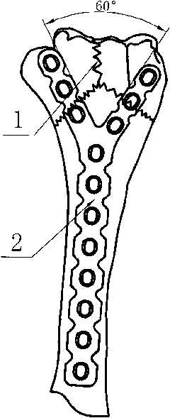
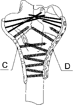
[0027] Such as Figure 4 , 5 , 6a, 6b and Figure 7a , 7b , 7c, a posterolateral distal humerus locking bone plate, which includes a head 1 and a body 2, and the head 1 and body 2 are integrally structured. The head 1 is wider than the body 2 . The body part 2 is straight, and the head 1 is extended from the upper end of the body part 2, and takes the center line of the body part as the axis-while extending, helically rotates and deviates toward the posterolateral E side of the distal end of the humerus. When rotating about 1 / 4 of a circle (that is, when the top of the steel plate head is basically perpendicular to the body of the steel plate), the rotation deviation L of the small plane at the top of the steel plate head 1 (the plane of the head and the centerline of the body) reaches 25-30mm (See Figure 7b ). When the bone plate with such a shape is in use, the body can be attached to the shaft of the humerus, and the head 1 can be attached to the fan-shaped posterior...


PUM


Abstract

The invention relates to a locking bone fracture plate for the far back outer side of humerus, which is a locking bone fracture plate for the far end of the humerus mainly used for treating humeral condylar fracture and fracture of humeral shaft, wherein a short steel plate can also be used for conveniently treating the humeral condylar fracture. The steel plate comprises a head and a body and is divided into a left part and a right part. The head of the steel plate is slightly wider than the body; the shape of the body of the steel plate is straight; the shape of the head of the steel plate rotates to the oblique edge of the head edge from the body; when the shape of the head rotates to the end, the plane of the steel plate rotates about 90 DEG; when the steel plate is used in the shape, the body of the steel plate is attached to the shaft of the humerus and the head of the steel plate is attached to the back side and the outer side of the condyle of the humerus; the head of the steel plate is provided with eight bolt holes, wherein bolts on the first hole, the second hole and the third hole can penetrate through the condyle of the humerus.

Description

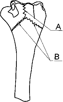
technical field [0001] The invention relates to an orthopedic internal fixation bone plate, in particular to a posterolateral locking bone plate for the treatment of humeral condyle fractures and humeral condyle fractures combined with humeral shaft fractures. technical background [0002] The human humeral condyle is shaped like a wide and flat fan. The humeral condyle of this shape is prone to fracture due to its flatness, and there are many types of humeral condyle fractures, for example: intercondylar fracture of the humerus (see figure 1 Middle fracture line A), supracondylar fracture of humerus (see figure 1 Middle fracture line B) and humeral intercondylar fracture combined with humeral supracondylar fracture (clinically called T-shaped fracture, and this kind of fracture is relatively common), in addition, humeral condyle fracture combined with humeral shaft fracture is often encountered clinically. [0003] For many years, most hospitals have used Y-shaped steel pl...

Claims


Application Information

Patent Timeline
IPC IPC(8): A61B17/80
Inventor 郭谦
Owner 北京理贝尔生物工程研究所有限公司
Learn More