Electrical structure of solid combination switch

A composite switch and electrical technology, applied in the direction of reactive power compensation, reactive power adjustment/elimination/compensation, etc., can solve the problems of inability to apply high-voltage systems, small reactive power compensation capacity, low electrical insulation capacity, etc., and achieve floor space Small size, less external wiring, and simple overall structure

Active Publication Date: 2012-07-18
CHINA EPRI SCIENCE & TECHNOLOGY CO LTD +2
View PDF1 Cites 0 Cited by
  • Summary
  • Abstract
  • Description
  • Claims
  • Application Information

AI Technical Summary

Problems solved by technology

However, the device has low electrical insulation capacity and small reactive power compensation capacity, so it cannot be applied to high-voltage systems.

Method used


Image

  • Electrical structure of solid combination switch
  • Electrical structure of solid combination switch
  • Electrical structure of solid combination switch

Examples


Embodiment Construction

[0020] Below, the present invention will be further described in conjunction with the accompanying drawings.

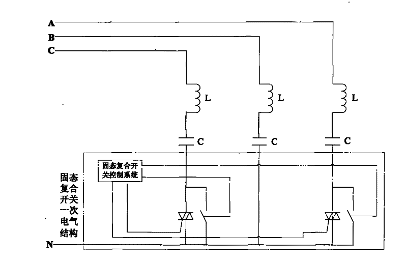
[0021] figure 1 It is the electrical structure diagram of the primary system of the solid-state composite switch. In the figure, A, B, and C are the three-phase buses of the system, and N is the neutral point of the filter branch of the capacitor bank. The three-phase busbars are respectively connected to reactors, and then the reactors and capacitors are connected in series. The outlets of the A and C two-phase capacitors are connected to the first end of the thyristor valve string, and the thyristor valve string is connected in parallel with the contactor. Terminal and B-phase capacitor outlet are shorted. This connection method is mainly aimed at the synchronous switching method of the three-phase capacitor bank. When the contactor is disconnected and the thyristor is not triggered, the B phase cannot form a current loop with other phases, so the B phase capacito...


PUM


Abstract

The invention relates to an electrical structure of a solid combination switch which can switch automatically; a three-phase system busbar incoming line is connected with a series reactor, the line outgoing from the reactor is connected with a capacitor, the outgoing line end of an A-C phase capacitor is connected with two groups of thyristor valve strings, the valve strings are connected with a contactor in parallel and then are short-connected with the outgoing line of a B-phase capacitor; a wall feed-through sleeve, a bus connecting copper bar, a thyristor valve string, an insulator, a thyristor valve high potential electric board (TE board), a TE board energy delivery power supply, a high-frequency converter, a high-voltage cable, an energy delivery magnet ring transformer, a vacuum contactor, a valve base electronic device (VBE), a regulating unit and a man-machine interface part are integrated together by an equipment cabinet, the equipment cabinet can be directly hung a high-voltage electric power system, so as to ensure the insulation of high-low voltage systems; in addition, the contact can be switched at the zero crossing point under the reactive power condition of the system, and the solid combination switch can be operated on the equipment cabinet in the running process.

Description

technical field [0001] The invention relates to an electrical structure of a solid-state composite switch applied to a power system, and a control device can automatically or manually switch a contactor under the condition of no arc. Background technique [0002] At present, solid-state composite switches used in power electronic equipment are mainly used in low-voltage power systems, using thyristors and relays in parallel, and using analog circuits for control. For example, Chinese patent application: 200720178283 discloses an intelligent composite switch, including switch shell , high-voltage incoming line terminal, intelligent analog control circuit, zero-crossing trigger and pulse drive circuit, thyristor and relay circuit in parallel with it. However, the device has low electrical insulation capacity and small reactive power compensation capacity, so it cannot be applied to high-voltage systems. Contents of the invention [0003] In order to apply the solid-state co...

Claims


Application Information

Patent Timeline
Patent Type & Authority Patents(China)
IPC IPC(8): H02J3/18
CPCY02E40/30
Inventor 李鹏李卫国马海超刘宏李志友赵刚
Owner CHINA EPRI SCIENCE & TECHNOLOGY CO LTD
Why Eureka
Try Eureka