
Combined heat and power system for directly recovering exhaust afterheat of power station steam turbine by absorption heat pump

An absorption heat pump and combined heat and power technology, which is applied in steam engine installations, steam applications, mechanical equipment, etc., can solve the problems of increasing investment in water pump power consumption of waste hot water systems, improve comprehensive energy utilization efficiency, and eliminate heat exchange temperature. Loss, easy-to-use effect

Inactive Publication Date: 2010-08-04
SHUANGLIANG ECO ENERGY SYST CO LTD
View PDF0 Cites 14 Cited by
  • Summary
  • Abstract
  • Description
  • Claims
  • Application Information

AI Technical Summary

Problems solved by technology

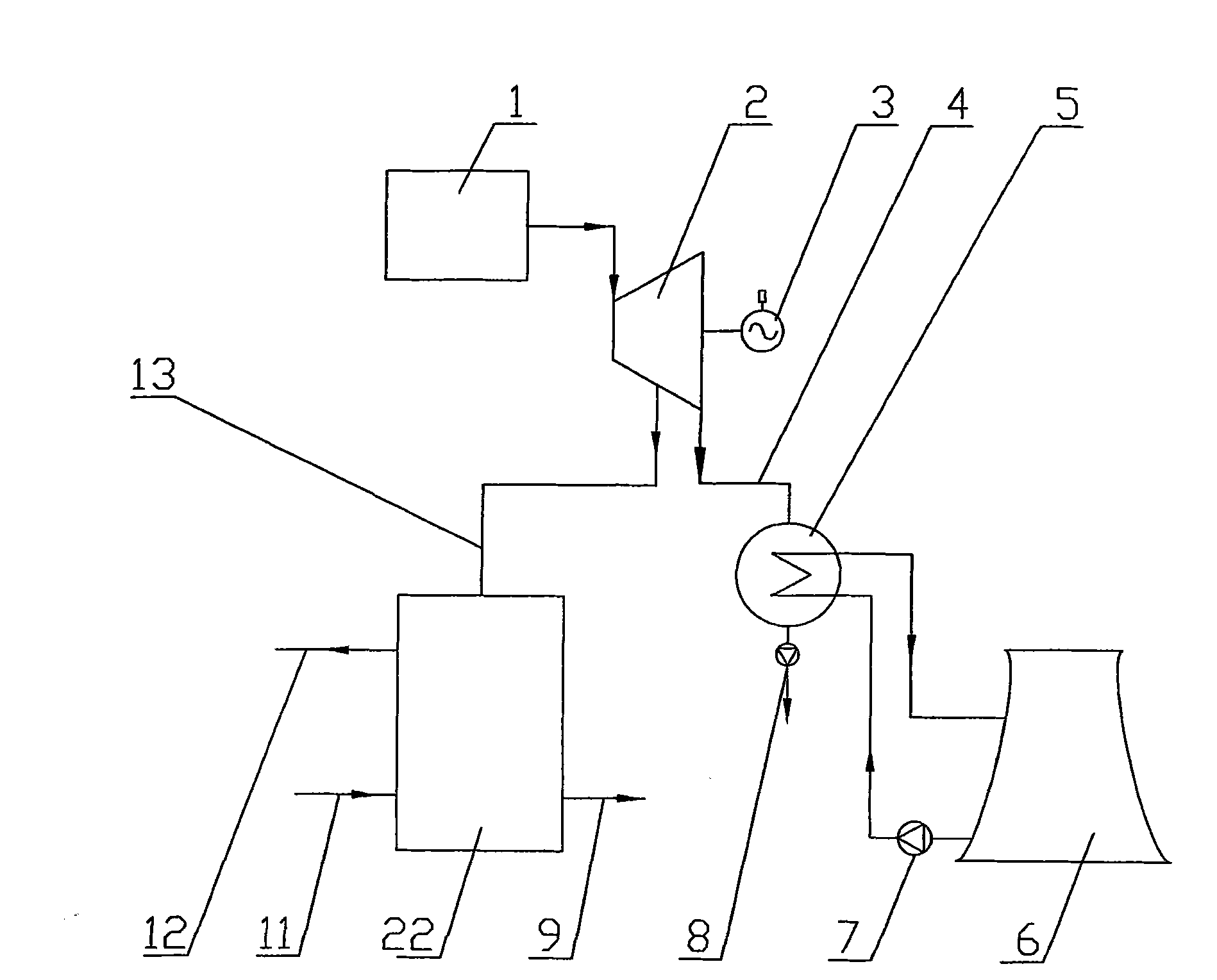
However, this kind of indirect extraction of steam turbine exhaust waste heat through waste water will increase the investment of waste water system (especially for air-cooling systems), the power consumption of water pumps, and the temperature loss caused by heat exchange between exhaust steam and waste water will affect the centralized supply. Unfavorable factors such as hot water temperature rise

Method used


Image

  • Combined heat and power system for directly recovering exhaust afterheat of power station steam turbine by absorption heat pump
  • Combined heat and power system for directly recovering exhaust afterheat of power station steam turbine by absorption heat pump
  • Combined heat and power system for directly recovering exhaust afterheat of power station steam turbine by absorption heat pump

Examples


Embodiment Construction

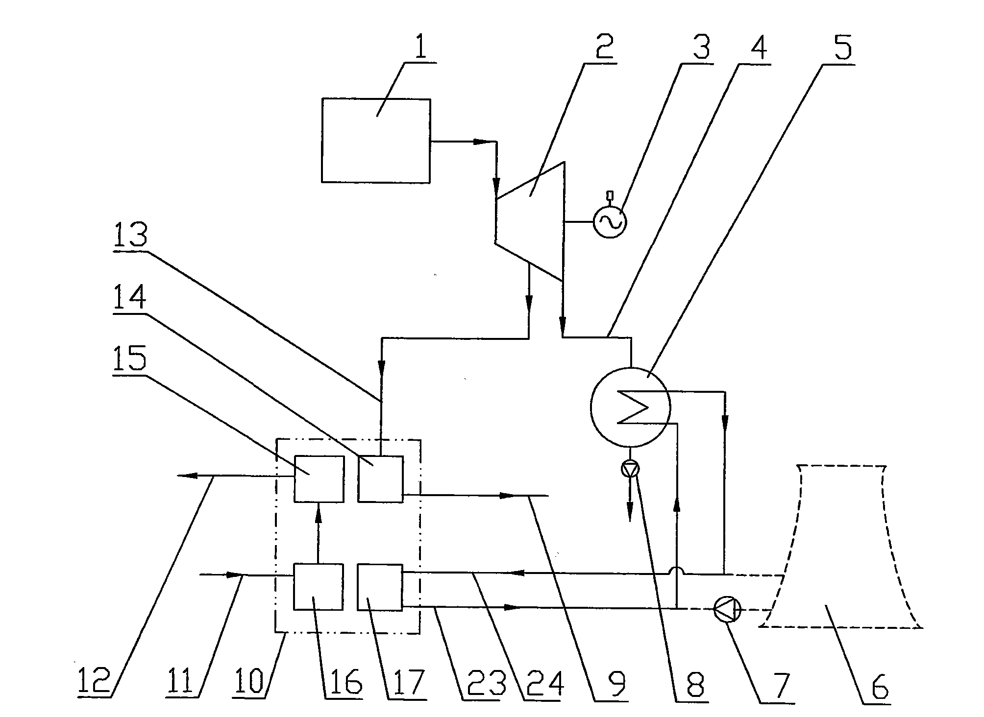
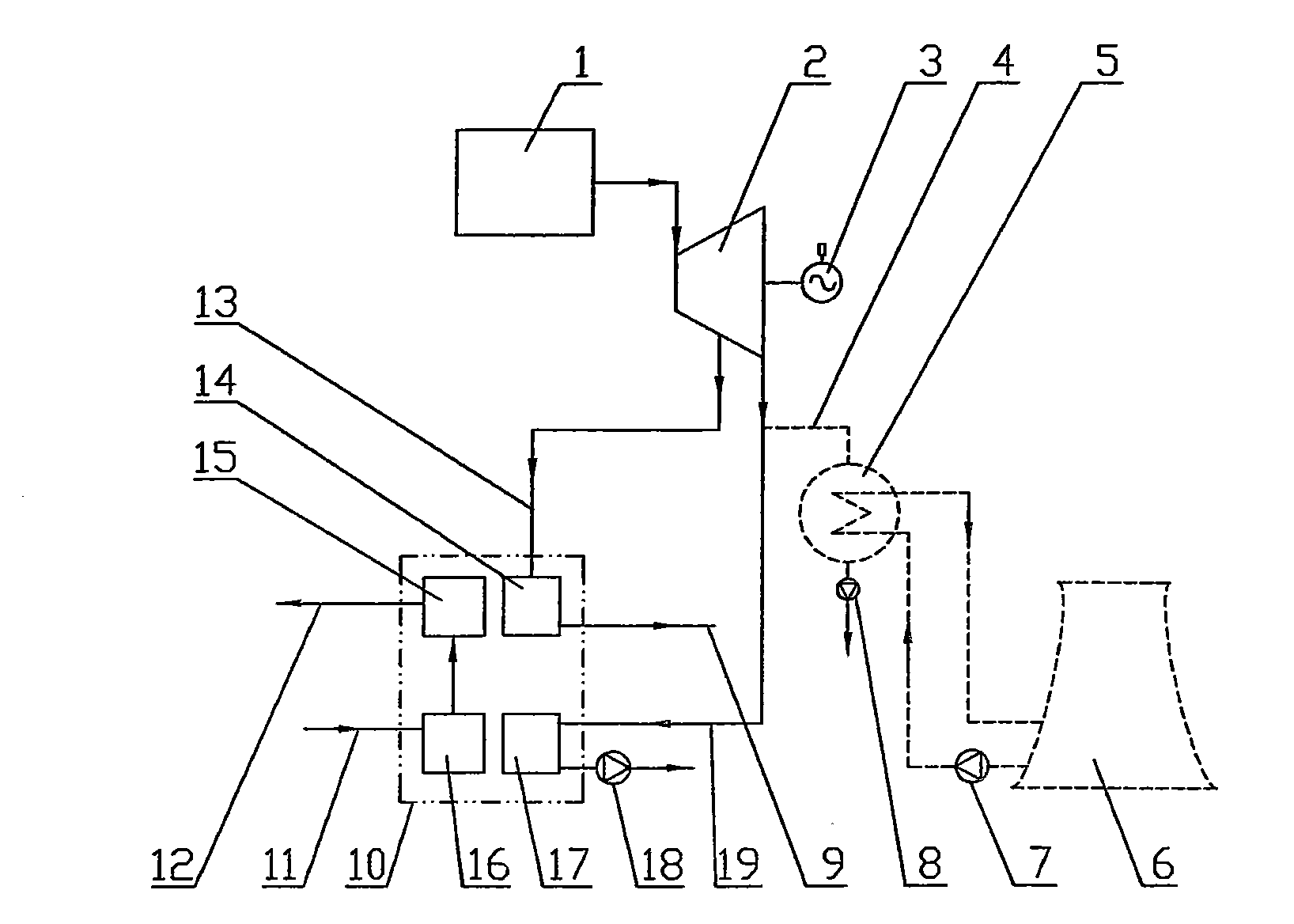
[0013] Such as image 3 Shown is a schematic diagram of a combined heat and power system that uses circulating water to cool the exhaust steam of the steam turbine and uses an absorption heat pump to directly recover the waste heat from the exhaust steam of the power station turbine. Power plant boiler 1, steam turbine 2, generator 3, steam turbine exhaust pipe 4, condenser 5, cooling tower (or air cooling system) 6, circulating water pump 7, exhaust condensate pump 8, steam extraction condensate return boiler pipe 9 , absorption heat pump 10, hot water return pipe 11, hot water outlet pipe 12, steam turbine extraction pipe 13, exhaust condensed water outlet evaporator pump 18 and steam turbine exhaust steam inlet evaporator pipe 19 and control system (not shown in the figure output) and other components of the absorption heat pump to directly recover the steam turbine exhaust heat cogeneration system of the power station. The absorption heat pump 10 is composed of a generato...


PUM


Abstract

The invention relates to a combined heat and power system for directly recovering exhaust afterheat of a power station steam turbine by an absorption heat pump, which is used for recovering the exhaust afterheat of the power station steam turbine. The combined heat and power system comprises a power plant boiler (1), the steam turbine (2), an electric generator (3), a steam turbine exhaust pipe (4), a condenser (5), a cooling tower or an air cooling system (6), a water circulating pump (7), an exhaust condensate pump (8), a steam extraction and water condensation boiler pipe (9), the absorption heat pump (10), a hot water return pipe (11), a hot water outlet pipe (12) and a steam turbine extraction pipe (13), wherein the absorption heat pump (10) comprises a generator (14), a condenser (15), an absorber (16) and an evaporator (17). The combined heat and power system is characterized in that: low-pressure steam pipes discharged by the steam turbine (2) are divided into two paths, wherein one path is connected with the condenser (5) through the steam turbine exhaust pipe (4), while the other path is connected with the evaporator (17) of the absorption heat pump (10) through a steam turbine exhaust evaporator tube (19). The combined heat and power system can more effectively recycle low-grade exhaust condensation heat of a power plant, and reduces the temperature loss, improves the supply water temperature of hot water, and reduces the system investment and operating cost on the premise of not changing the exhaust back pressure.

Description

(1) Technical field [0001] The invention relates to an absorption heat pump system for directly recovering waste heat from exhaust steam of a steam turbine in a power station. It is used to recover the exhaust heat of steam turbines in power stations. (2) Background technology [0002] my country's winter heating, urban central heating, production process central heating and other hot water pipe networks adopt the centralized heating mode of combined heat and power in thermal power plants in many cases. Even in heating conditions, there is still a large amount of low-grade exhaust steam waste heat after steam turbine power generation that cannot be utilized, and is discharged into the atmosphere through circulating water (usually through cooling towers) or air cooling systems, affecting the overall efficiency of energy utilization. [0003] Such as figure 1 As shown, at present, the hot water for central heating generally adopts the medium-pressure steam (generally 0.3-1.0...

Claims


Application Information

Patent Timeline
Patent Type & Authority Applications(China)
IPC IPC(8): F01K17/04
CPCY02E20/14
Inventor 江荣方毛洪财王炎丽
Owner SHUANGLIANG ECO ENERGY SYST CO LTD
Learn More