Mixed flow expanded bed anaerobic microorganism filter tank

An anaerobic biofilter and biofilter technology, applied in the field of mixed flow expanded bed anaerobic biofilter, can solve the problem of anaerobic suspension filler without pre-hanging film treatment, complex structure of falling water aeration unit, anaerobic suspension Problems such as the small amount of film hanging on the filler, etc., are beneficial to the development of the industry and popularization and application, improve the uniformity of water distribution, and save the effect of aeration power devices

Inactive Publication Date: 2010-08-04
BEIJING NEWATT ENVIRONMENTAL ENG CO LTD
View PDF2 Cites 1 Cited by
  • Summary
  • Abstract
  • Description
  • Claims
  • Application Information

AI Technical Summary

Problems solved by technology

[0009] The purpose of the present invention is to provide an improved non-powered sewage biological purification device to solve the problem of large floor area and insufficient effective water depth in the prior art, which affects the anaerobic reaction efficiency; the steel shell is easy to corrode; anaerobic suspension The film-hanging amount of the filler is small, which affects the anaerobic reaction efficiency; the water distribution uniformity of the water inlet and water distribution pipes is poor; there is no sludge suction device, which is inconvenient to maintain; the anaerobic suspension filler has no pre-film-hanging treatment, and it cannot be used after filling. The whole system can be connected and used immediately; the structure of the drop water aeration unit is relatively complicated, which requires an aerator, and the power consumption is large, so it is not easy to cause problems in mass production

Method used


Image

  • Mixed flow expanded bed anaerobic microorganism filter tank
  • Mixed flow expanded bed anaerobic microorganism filter tank
  • Mixed flow expanded bed anaerobic microorganism filter tank

Examples


Embodiment Construction

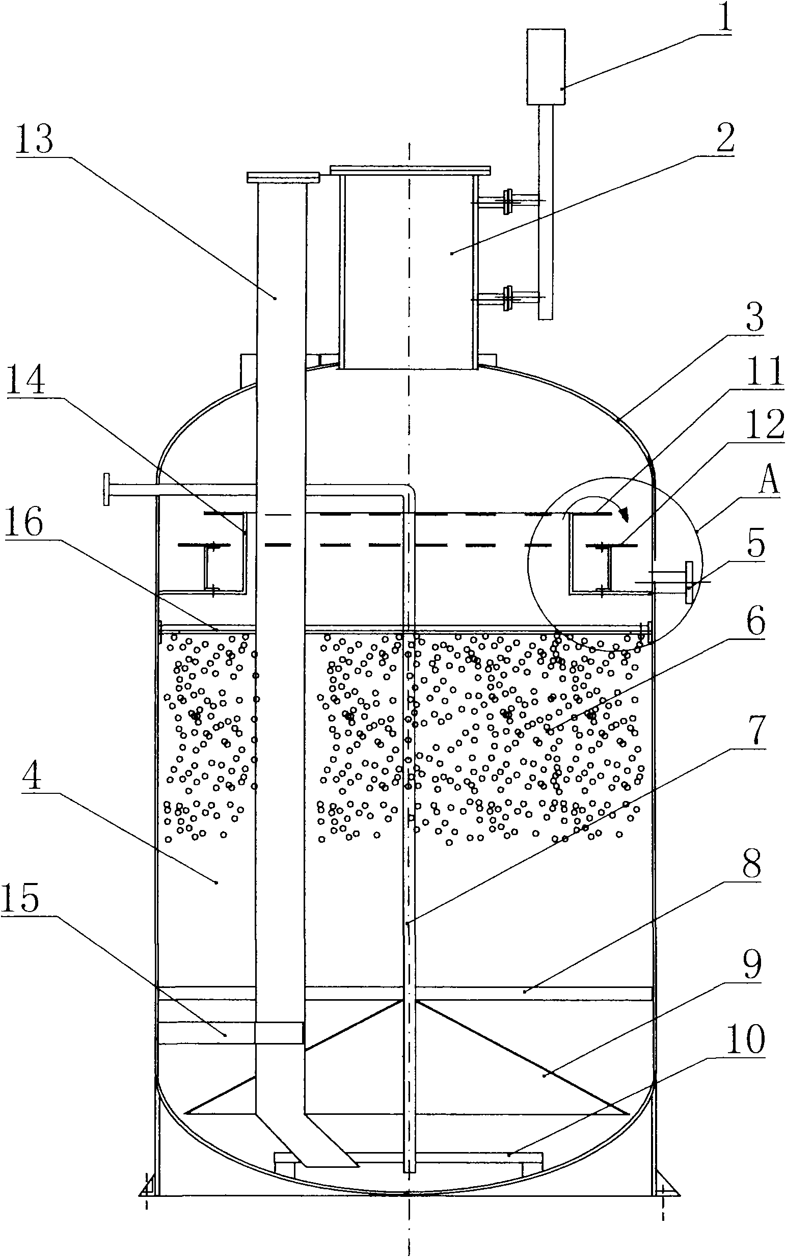
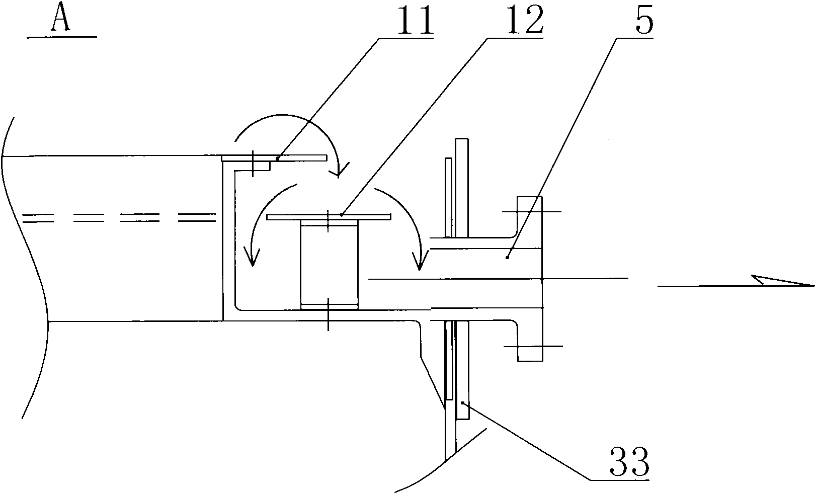
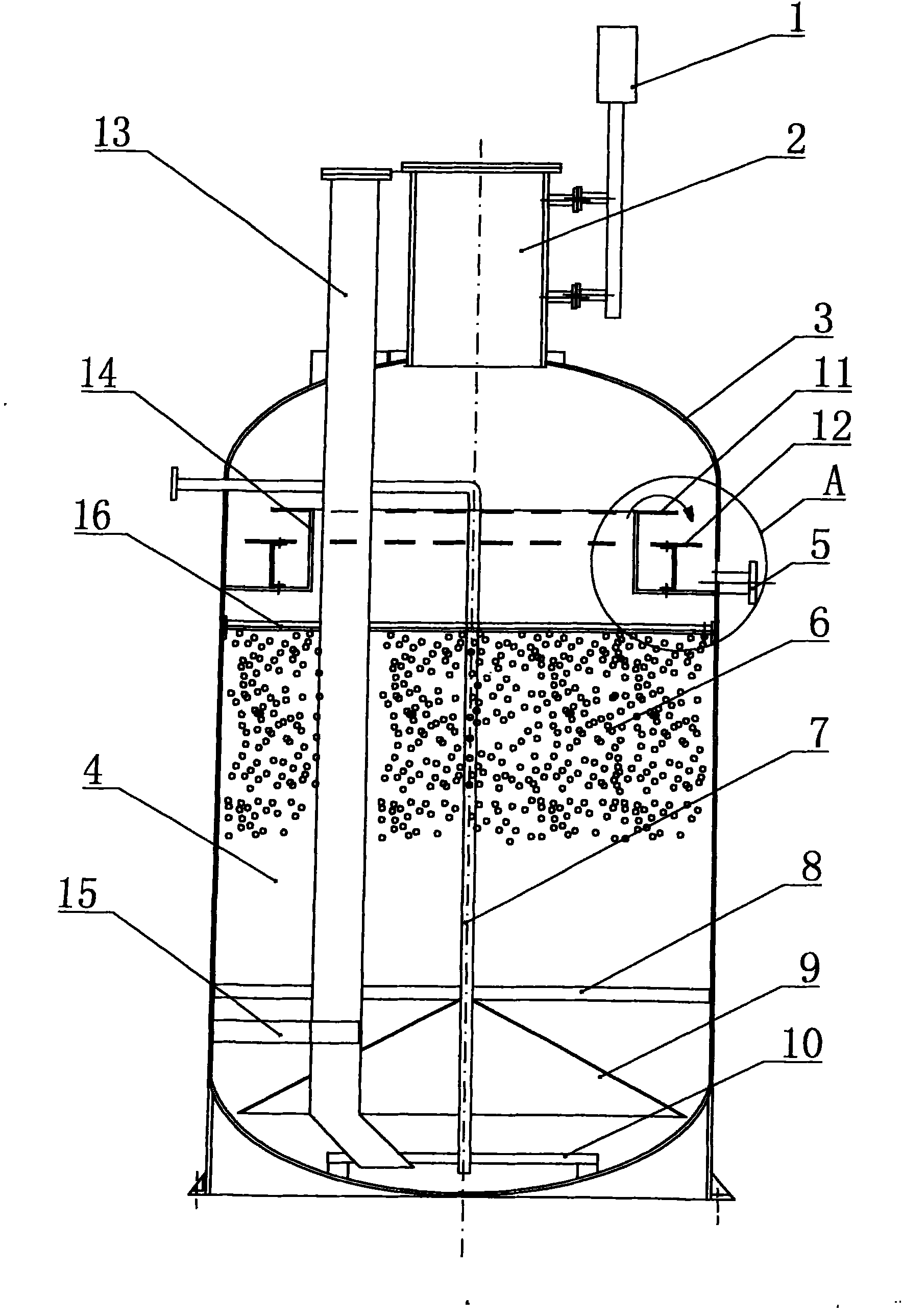
[0024] see figure 1 and figure 2 , the present invention includes a biological filter 4 located in the middle and lower part of the glass fiber reinforced plastic cylindrical tank body 3, a constriction 14 is provided at the upper end of the biological filter 4, and the drop water is provided on the outer edge of the constriction 14 In the aeration unit A, a spacer 16 is arranged in the constriction of the upper end of the biological filter 4 , and an anaerobic suspension filler 6 is arranged below the spacer 16 . A water distributor 9 is installed at the bottom of the biofilter 4, and the water inlet pipe 7 and the dredging pipe 13 are passed longitudinally on the water distributor 9, and the upper ends of the water inlet pipe 7 and the mud suction pipe 13 pass through the described The upper part of the glass fiber reinforced plastic cylindrical tank body 3. The mud suction pipe 13 can conveniently extract excess sludge at the bottom of the tank body, and can also be used...


PUM


Abstract

The invention relates to a mixed flow expanded bed anaerobic microorganism filter tank, comprising a casing which is a cylindrical glass fiber reinforced plastic tank body. A biofilter is arranged at the lower-middle part of the cylindrical glass fiber reinforced plastic tank body; the upper end of the biofilter is provided with a shrink mouth; the outer edge of the shrink mouth is provided with a drop-aeration device; a mesh is arranged in the upper port of the biofilter; anaerobic suspended filler is arranged below the mesh; a water distributor is in a shape of an umbrella; a water inlet pipe and a mud sucking pipe longitudinally pass through the water distributor; and the upper ends of the water inlet pipe and the mud sucking pipe are respectively penetrate through the upper part of the cylindrical glass fiber reinforced plastic tank body. The filter tank has small occupied area, difficult erosion of the steel casing, large amount of biofilm formation, increase of anaerobic reaction efficiency, good water distribution evenness of the water inlet pipe and a water distributing pipe and convenient maintenance by additionally arranging a mud sucking device; the anaerobic suspended filler can be used for precoating treatment to realize the instant use of the whole system after loading; and the drop-aeration does not have power consumption, so that standardization and batch production is easy to realize, and the filter is easy to popularize.

Description

technical field [0001] The invention relates to a mixed flow expanded bed anaerobic biological filter, which is mainly used for anaerobic biological treatment of various organic sewage. Background technique [0002] The prior art (Patent No. ZL200420112057.2) discloses a "non-powered sewage biological purification device", its main structure includes a mixed flow expanded bed anaerobic biological treatment unit and a falling water aeration unit, all placed in a closed In the casing, the mixed flow expanded bed anaerobic biological treatment unit includes a biofilter and a water distribution pipe, the water distribution pipe is installed at the bottom of the biofilter, and a water inlet pipe is connected to the water distribution pipe; a suspension is provided in the biofilter Filling, the upper end of the biological filter is the water outlet; the falling water aeration unit includes at least one aeration ladder, and the upper end of each aeration ladder is the water outlet ...

Claims


Application Information

Patent Timeline
Patent Type & Authority Applications(China)
IPC IPC(8): C02F3/28
Inventor 朱向宏张敏
Owner BEIJING NEWATT ENVIRONMENTAL ENG CO LTD
Why Eureka
Try Eureka