
Binocular video synchronous acquisition equipment

A technology of synchronous acquisition and binocular video, applied in image communication, electrical components, stereo systems, etc., can solve difficult binocular stereo matching processing, affect the performance and real-time performance of the stereo vision system, and cannot realize the pixels of binocular video data. Level synchronization storage and transmission and other issues

Inactive Publication Date: 2011-10-05
SERVICE CENT OF COMMLIZATION OF RES FINDINGS HAIAN COUNTY
View PDF0 Cites 0 Cited by
  • Summary
  • Abstract
  • Description
  • Claims
  • Application Information

AI Technical Summary

Problems solved by technology

[0003] Existing multi-channel video acquisition modules usually use a time-sharing acquisition method, which cannot truly realize synchronous acquisition of two channels of video; in terms of storage and transmission, usually after completing the analog / digital sampling of video signals, the video data is directly transmitted to the host computer , even if there is data buffer storage, the circuit is relatively simple, and it is impossible to realize the pixel-level synchronous storage and transmission of binocular video data, as well as the seamless buffering and processing of binocular video data, and it is difficult to perform subsequent binocular stereo matching processing, seriously Affects the performance and real-time performance of the stereo vision system

Method used


Image

  • Binocular video synchronous acquisition equipment
  • Binocular video synchronous acquisition equipment
  • Binocular video synchronous acquisition equipment

Examples


Embodiment Construction

[0024] The present invention will be further described below in conjunction with accompanying drawing.

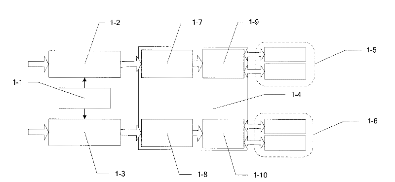
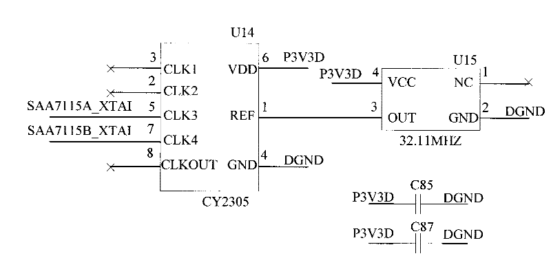
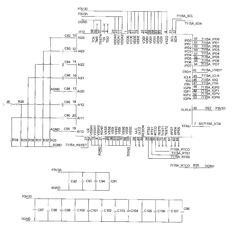
[0025] Such as figure 1 As shown, the binocular video synchronous acquisition device includes a clock synchronization circuit 1-1, a first video decoding circuit 1-2, a second video decoding circuit 1-3, a programmable logic device 1-4, a first storage buffer circuit 1- 5 and the second storage buffer circuit 1-6. Among them, the first video decoding chip interface control circuit 1-7, the second video decoding chip interface control circuit 1-8 are obtained by programming the programmable device, respectively together with the first video decoding circuit and the second video decoding circuit, two video decoding circuits are completed. The design of one-way video acquisition circuit realizes the synchronous acquisition of two-way video. The first ping-pong storage control module 1-9 and the second ping-pong storage control module 1-10 are obtained by programming the prog...


PUM


Abstract

The invention relates to binocular video synchronous acquisition equipment. The conventional multi-channel video acquisition module adopts a time-sharing acquisition way and cannot really realize double-channel video synchronous acquisition. The binocular video synchronous acquisition equipment comprises a clock synchronous circuit, a first video decoding circuit, a second video decoding circuit,a programmable logic device, a first memory buffer circuit and a second memory buffer circuit, wherein the first video decoding circuit is in signal connection with a first input end of the programmable logic device and the second video decoding circuit is in signal connection with a second input end of the programmable logic device; the clock synchronous circuit is in signal connection with the first video decoding circuit and the second video decoding circuit respectively and provides clock signals for the first video decoding circuit and the second video decoding circuit; and the first output end of the programmable logic device is in signal connection with the first memory buffer circuit and the second output end of the programmable logic device is in signal connection with the secondmemory buffer circuit. The binocular video synchronous acquisition equipment realizes clock synchronization of two channels of video decoding chips and seamless buffer storage of the two channels of video data.

Description

technical field [0001] The invention belongs to the technical field of computer stereo vision, and in particular relates to a binocular video synchronous acquisition device. Background technique [0002] Binocular video acquisition is the prerequisite and key technology for realizing binocular stereo vision system. The main difficulties in binocular video acquisition are: (1) clock synchronization of binocular video decoding chips; (2) seamless buffer storage of binocular video data; (3) synchronous storage of binocular video data at the pixel level. [0003] Existing multi-channel video acquisition modules usually use a time-sharing acquisition method, which cannot truly realize synchronous acquisition of two channels of video; in terms of storage and transmission, usually after completing the analog / digital sampling of video signals, the video data is directly transmitted to the host computer , even if there is data buffer storage, the circuit is relatively simple, and it...

Claims


Application Information

Patent Timeline
Patent Type & Authority Patents(China)
IPC IPC(8): H04N13/02
Inventor 周文晖刘广飞
Owner SERVICE CENT OF COMMLIZATION OF RES FINDINGS HAIAN COUNTY
Learn More