
Lock chamber energy dissipating open ditch of ship lock

A lock chamber and open ditch technology, applied in ship locks, ship lifting devices, buildings, etc., can solve the problems of limited application scope of energy dissipation in single open ditch, complicated layout of water delivery systems in lock chambers, unfavorable water flow diffusion and energy dissipation, etc. The effect of reducing the number of sluice chamber corridors, reducing the local water surface height, and improving the energy dissipation efficiency

Inactive Publication Date: 2010-07-28
NANJING HYDRAULIC RES INST
View PDF0 Cites 12 Cited by
  • Summary
  • Abstract
  • Description
  • Claims
  • Application Information

AI Technical Summary

Problems solved by technology

[0003] The inventor's previous research shows that the energy dissipation of the sluice chamber has certain requirements on the open ditch. If the size of the open ditch exceeds a certain range, it will not be conducive to the diffusion and energy dissipation of the water flow. Therefore, the application range of the single open ditch energy dissipation is limited.
In order to make the distribution of water flow in the lock chamber more uniform, it is necessary to increase the number of corridors, which leads to complex layout of the water delivery system in the lock chamber, increased engineering investment, and at the same time reduces the energy dissipation water body and reduces the energy dissipation effect, which is especially important for the lock chamber. The layout of the water delivery system of the bottom transverse branch corridor has a greater influence

Method used


Image

  • Lock chamber energy dissipating open ditch of ship lock
  • Lock chamber energy dissipating open ditch of ship lock
  • Lock chamber energy dissipating open ditch of ship lock

Examples


Embodiment 1

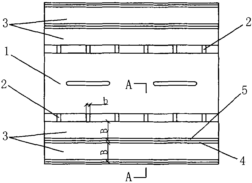
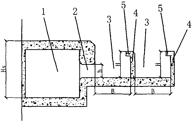
[0025] The energy-dissipating open ditch of the lock chamber of the present embodiment, such as figure 1 and figure 2 As shown, it includes the lock chamber adopting the distributed water delivery system of the side branch holes of the longitudinal corridor at the bottom of the lock chamber (only a section of the lock chamber is reflected in the figure), and the lock chamber corridor 1 is arranged along the longitudinal length of the lock chamber, and the lock chamber corridor 1 The bottoms of both sides are provided with side outlet branch holes 2 arranged at intervals, and an open ditch 3 surrounded by stilling sills 4 spaced apart from each other is provided outside the outlet branch hole 2, wherein the open ditch 3 on the side of the outlet branch hole 2 has Second way. Two open ditches 3 are arranged along the longitudinal length of the sluice chamber, and a horizontal baffle 5 protruding toward the water outlet branch hole 2 is arranged on the top of the stilling sill ...

Embodiment 2

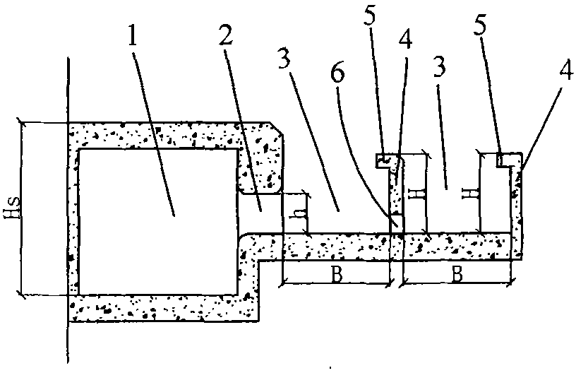
[0028] The energy-dissipating open ditch in the lock chamber of this embodiment is as follows: image 3 As shown, it is basically the same structure as the energy-dissipating open ditch of the ship lock chamber in Embodiment 1, the difference is that water permeable holes 6 arranged at intervals are arranged in the middle of the stilling sill 4 .

Embodiment 3

[0030] The energy-dissipating open ditch in the lock chamber of the present embodiment is an improvement on the basis of Embodiment 1, as Figure 4 and Figure 5 As shown, the difference except that it is the same as that of Embodiment 1 is: 1) the lock chamber adopts a decentralized water delivery system of the longitudinal main corridor of the gate wall and the horizontal branch corridor at the bottom of the gate, and the transverse branch corridor is the lock chamber corridor 1 , the main corridor 101 is located in the gate walls 100 on both sides, the main corridor 101 is connected with the lock chamber corridor 1 (horizontal branch corridor), and the lock chamber corridor 1 (horizontal branch corridor) is located at the bottom of the lock chamber and along the gate The chambers are horizontally arranged in a staggered conical shape; 2) The upper side and the side of the outlet of the outlet branch hole 2 are respectively provided with a shroud 7 and a diversion pier 8 . ...


PUM


Abstract

The invention relates to a lock chamber energy dissipating open ditch of a ship lock, which belongs to the technical field of ship lock hydraulic buildings. The lock chamber energy dissipating open ditch of a ship lock comprises open ditches, wherein the open ditches are arranged outside a lock chamber gallery water outlet branch hole in a lock chamber of the ship lock and enclosed by force dissipating sills which are mutually spaced; one side of the water outlet branch hole is provided with at least two open ditches; and the force dissipating sills are provided with a water permeating hole or distributed into a step shape from a low part to a high part from the water outlet branch hole to the outer side. Compared with a single open ditch of the lock chamber of the traditional ship lock, the lock chamber energy dissipating open ditches of a ship lock can increase the energy dissipating volume for flowing out of the lock chamber gallery water outlet branch hole manifold and reduce the water flow turbulence and high local water surface in the lock chamber, thereby improving the energy dissipating efficiency and the safety of the ship to be locked in the lock chamber manifold, reducing the quantity of lock chamber galleries, simplifying the lock chamber structure, and reducing the engineering investment.

Description

technical field [0001] The invention relates to an open ditch structure for dissipating energy during the water filling process of a ship lock chamber, and belongs to the technical field of ship lock hydraulic structures. Background technique [0002] Ship lock is a navigation structure widely used in inland waterway shipping. Ships passing through the ship lock need to repeatedly fill and discharge the lock chamber through the water delivery system to overcome the concentrated water level difference of the ship lock and ultimately ensure the safety of the ship's berthing and navigation. During the repeated water delivery process of the ship lock, in order to consume a large amount of energy brought by the water flow entering the lock chamber and meet the berthing conditions of the ships in the lock chamber, various longitudinal or horizontal corridors with water outlet holes are often arranged in the lock chamber to adjust the flow distribution. , These water outlets can be...

Claims


Application Information

Patent Timeline
IPC IPC(8): E02C1/08
Inventor 宣国祥宗慕伟李云黄岳李君
Owner NANJING HYDRAULIC RES INST
Learn More