
Time synchronization method, device and system of xDSL

A time synchronization and time technology, applied in the field of communication, can solve problems such as large line noise, affecting the accuracy of time synchronization, large errors, etc., and achieve the effect of time synchronization

Active Publication Date: 2010-07-21
HUAWEI TECH CO LTD
View PDF1 Cites 15 Cited by
  • Summary
  • Abstract
  • Description
  • Claims
  • Application Information

AI Technical Summary

Problems solved by technology

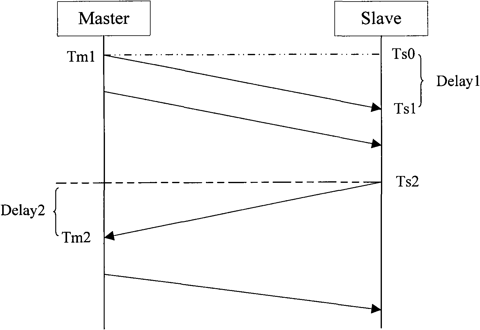
[0013] The xDSL receiver will detect the frame boundary and realize frame synchronization during the initialization process. In actual implementation, there may be a little error in the synchronization algorithm, and the synchronization accuracy is also limited by the sampling rate. The frame synchronization error may affect the accuracy of time synchronization. Spend
For example, the sending end uses the beginning of a certain frame as the time stamp tm1 (CO) or time stamp ts2 (CPE), when the CPE receiving end performs time marking Ts1 or when the CO receiving end performs time marking Tm2, ​​its frame synchronization is The receiving end restores it through a certain algorithm, and generally there is a certain error. Due to the existence of this frame synchronization error, xDSL may have a large error when performing Ts1 marking on the CPE and Tm2 marking on the CO, especially in the uplink. When the middle CO receives Tm2 mark, because the xDSL sampling rate may be low, the magnitude of this error will be larger
[0014] Delay1 can also be obtained by directly measuring the delay time of the downlink channel, so that the delay time deviation Offset=Ts1-Tm1-Delay1 of the CO and the CPE can be directly obtained, but at present, the time delay measurement of the xDSL channel (mainly the line) is not yet Especially accurate, especially when the line is long, the line is noisy, and there are complex situations such as bridge taps on the line

Method used


Image

  • Time synchronization method, device and system of xDSL
  • Time synchronization method, device and system of xDSL
  • Time synchronization method, device and system of xDSL

Examples


Embodiment Construction

[0044] The present invention will be clearly and completely described below in conjunction with the accompanying drawings:

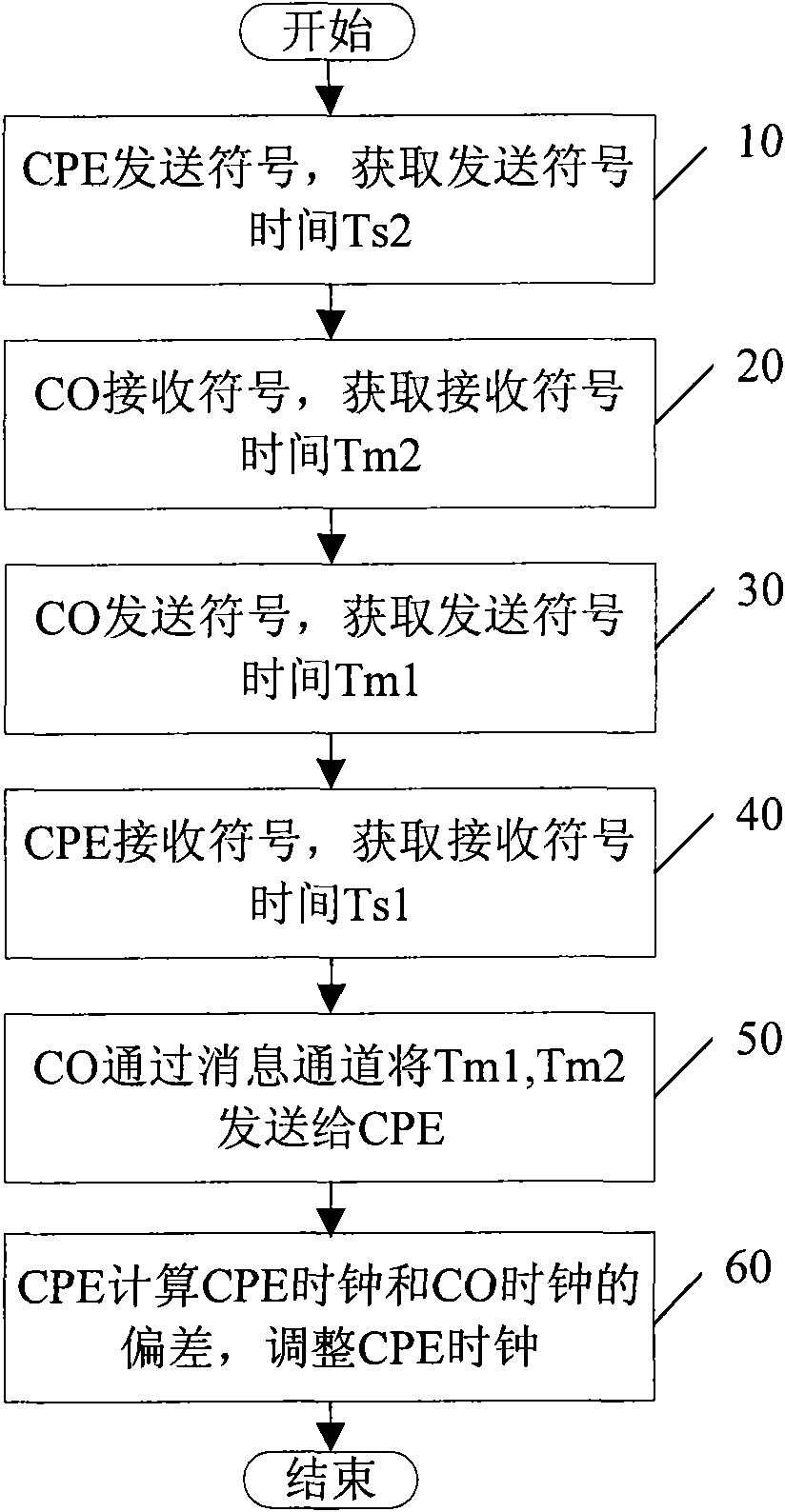
[0045] The first embodiment of the present invention provides an xDSL time synchronization method, including the following steps: the first device sends a first symbol to the second device, and obtains the time Ts2 for sending the first symbol;

[0046] The first device receives the second symbol sent by the second device, and acquires time Ts1 for receiving the second symbol;

[0047] The first device obtains the time Tm2 when the second device receives the first symbol and the time Tm1 when the second device sends the second symbol;

[0048] The first device calculates the deviation between the clock of the first device and the clock of the second device according to the Ts1, Ts2, Tm1, Tm2, ​​and the delay of the first device;

[0049] The first device adjusts a clock of the first device according to the offset to achieve synchronization. In the foll...


PUM


Abstract

The invention provides an xDSL time synchronization method, device and system. The method comprises the following steps: a far-end sends a first symbol, a local end receives the first symbol, the far-end obtains the time for sending the first symbol and the time for receiving the first symbol; the local end sends a second symbol, the far-end receives the second symbol, the far-end obtains the time for sending the second symbol and the time for receiving the second symbol, when calculating the clock offset of the far-end and the local end, the far-end splits the delay of path from the local end to the far-end and the delay of path from the far-end to the local end, obtains the value of the known part, and uses the condition that the downlink delay is approximately equal to the uplink delay or the downlink delay is proportional to the uplink delay to calculate the clock offset of the far-end and the local end, and the far-end uses the offset to adjust the clock and realize synchronization. The method of the invention can accurately obtain the clock offset of the far-end and the local end and effectively realize the time synchronization of the far-end and the local end by adjusting the read clock time of the far-end and the read clock time of the local end.

Description

technical field [0001] The present invention relates to the communication field, in particular to a method, device and system for xDSL time synchronization. Background technique [0002] Due to the emergence of the third generation of mobile communication (3G) and more advanced digital mobile technology, the demand for femtocells is increasing. Femtocells have relatively high requirements for time synchronization. Generally, clock synchronization is due to the fact that terminals of network devices have clock recovery modules. It is not difficult for the network to meet the clock synchronization of femtocells. However, the realization of time synchronization needs to solve many problems. figure 1 Shown is the schematic diagram of precise time synchronization in the IEEE Pl588V2 protocol. Assume that Offset is the deviation between the slave clock and the master clock, Delay1 is the path delay from the master clock to the slave clock, and Delay2 is the path delay from the sl...

Claims


Application Information

Patent Timeline
IPC IPC(8): H04L27/26H04L12/56H04M11/06H04Q11/04
CPCH04J3/0638H04L7/0041H04M11/062H04L7/027H04L27/00
Inventor 徐贵今龙国柱肖瑞杰赵治磊邬旭永贾玉臣
Owner HUAWEI TECH CO LTD
Learn More