Machining method for finely boring stand and finely bored stand thereof

A processing method and machine base technology, which is applied in the field of machine base fine boring and machine base fine boring processing, can solve the problems that the overall dimensional accuracy and runout accuracy of the machine base cannot meet the requirements of product drawings, uneven turning stress distribution, machine base shape and To solve problems such as heavy weight, achieve the effects of saving alignment time, improving dimensional accuracy and roughness accuracy, and improving the stability of the machine base

Inactive Publication Date: 2012-07-04
DALIAN TIANYUAN ELECTRICAL MACHINERY
View PDF0 Cites 0 Cited by
  • Summary
  • Abstract
  • Description
  • Claims
  • Application Information

AI Technical Summary

Problems solved by technology

[0002] Usually the machine base end face and inner circle are processed on a vertical lathe, leave a certain margin after rough turning the machine base end face and inner circle, and then use the finishing tire to position the finish car to the drawing size, and then stop on the milling machine Tire positioning milling, drilling foot, etc., the specific processing process is: rough turning-finish turning-milling, drilling foot-planing keyway-drilling, if the wind power series machine base and other large machine bases are processed by the above method, Due to the poor positioning accuracy of the spigot tire, it is easy to cause inaccurate positioning accuracy. In addition, the shape and weight of the machine base are large, especially the overall length is too long, which makes it difficult to clamp. The stability of the machine base is poor when it is erected, which easily leads to turning stress distribution. Unevenness, so the overall dimensional accuracy and runout accuracy of the machine base are not easy to meet the requirements of the product drawings. In addition, the front and rear feet of the machine base are prone to tilt when milling and drilling the feet

Method used


Image

  • Machining method for finely boring stand and finely bored stand thereof
  • Machining method for finely boring stand and finely bored stand thereof
  • Machining method for finely boring stand and finely bored stand thereof

Examples


Embodiment Construction

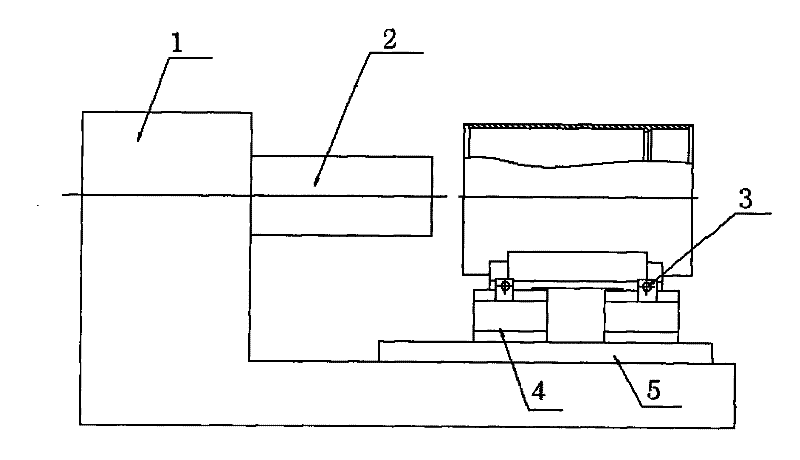
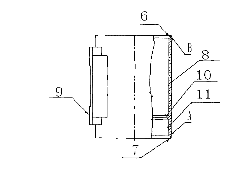
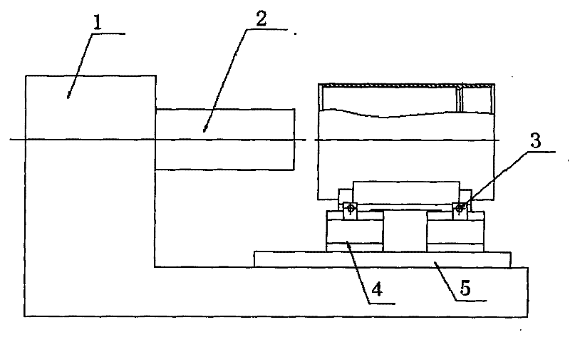
[0020] like figure 1 , figure 2 As shown, the base fine boring includes a boring machine 1, a boring machine head 2, a fine-tuning screw 3, a positioning tire 4 and a boring machine table 5; the machine base part includes a stopper 6, a stopper 7, an iron core 8, a foot plane 9, Block table 10 and empty tool place 11, the specific steps of the machine base fine boring processing method and the machine base fine boring processing method thereof are as follows:

[0021] 1. The machine base is vertically clamped on the vertical lathe in the traditional way, that is, the four-jaw chuck is used to clamp the machine base A, and after alignment, the stop (6) and the iron core of the rough turning machine base 1 mm machining allowance for the end face, 2 mm machining allowance for the diameter of the seam (6), and 1.5 mm machining allowance for the diameter of the iron core (that is, leave the machining allowance for fine boring once to the product drawing size); the machine base is...


PUM


Abstract

The invention discloses a machining method for finely boring a stand, which comprises the following concrete steps of: (A) roughly turning the stand on a vertical lathe, reserving 2mm diameter machining allowance in the length direction and on rabbets, reserving 1.5mm diameter allowance at the part of an iron core, and finely turning the rabbet at one end according to a set tolerance for milling,drilling and positioning pins; (B) positioning the stand on a numerically-controlled milling and drilling machine through rabbet tires, milling a bottom pin plane, and drilling bottom pin holes; (C) positioning the stand on a numerically-controlled horizontal stand single-sided boring machine by using high-precision tire plates through the bottom pin plane and the bottom pin holes, measuring the jumps of the front end surface, the back end surface and the rabbets of the stand by using a dial gauge for aligning the stand, then fixing the tire plates on a workbench to tightly press the stand, and finely boring the stand rabbet size, the total length size and the iron core size; and (D) when the finely bored stand is machined, aligning the first stand, directly installing other stands on thefixed tire plates, respectively measuring the jumps of the two end surfaces and the rabbets of the stand by using the dial gauge, and adjusting and aligning the fine boring precision through fine adjustment screws.

Description

technical field [0001] The invention relates to a machining method for a large machine base, in particular to a machine base fine boring processing method and the machine base fine boring. Background technique [0002] Usually the machine base end face and inner circle are processed on a vertical lathe, leave a certain margin after rough turning the machine base end face and inner circle, and then use the finishing tire to position the finish car to the drawing size, and then stop on the milling machine Tire positioning milling, drilling foot, etc., the specific processing process is: rough turning-finish turning-milling, drilling foot-planing keyway-drilling, if the wind power series machine base and other large machine bases are processed by the above method, Due to the poor positioning accuracy of the spigot tire, it is easy to cause inaccurate positioning accuracy. In addition, the shape and weight of the machine base are large, especially the overall length is too long,...

Claims


Application Information

Patent Timeline
Patent Type & Authority Patents(China)
IPC IPC(8): B23P23/02B23B41/00
Inventor 杨连春刘恩波刘永正殷淑芬张大庆蔡宇韩飞崔海龙
Owner DALIAN TIANYUAN ELECTRICAL MACHINERY
Why Eureka
Try Eureka