A Gravity Adjustable Rolling Tool
A technology of gravity and tools, which is applied in the field of gravity-type adjustable rolling tools, can solve the problems of complex control system equipment and instruments, and achieve the effects of low cost, convenient manufacture and simple structure
- Summary
- Abstract
- Description
- Claims
- Application Information
AI Technical Summary
Problems solved by technology
Method used
Image
Examples
Embodiment 1
[0031] This embodiment is carried out on a common lathe.
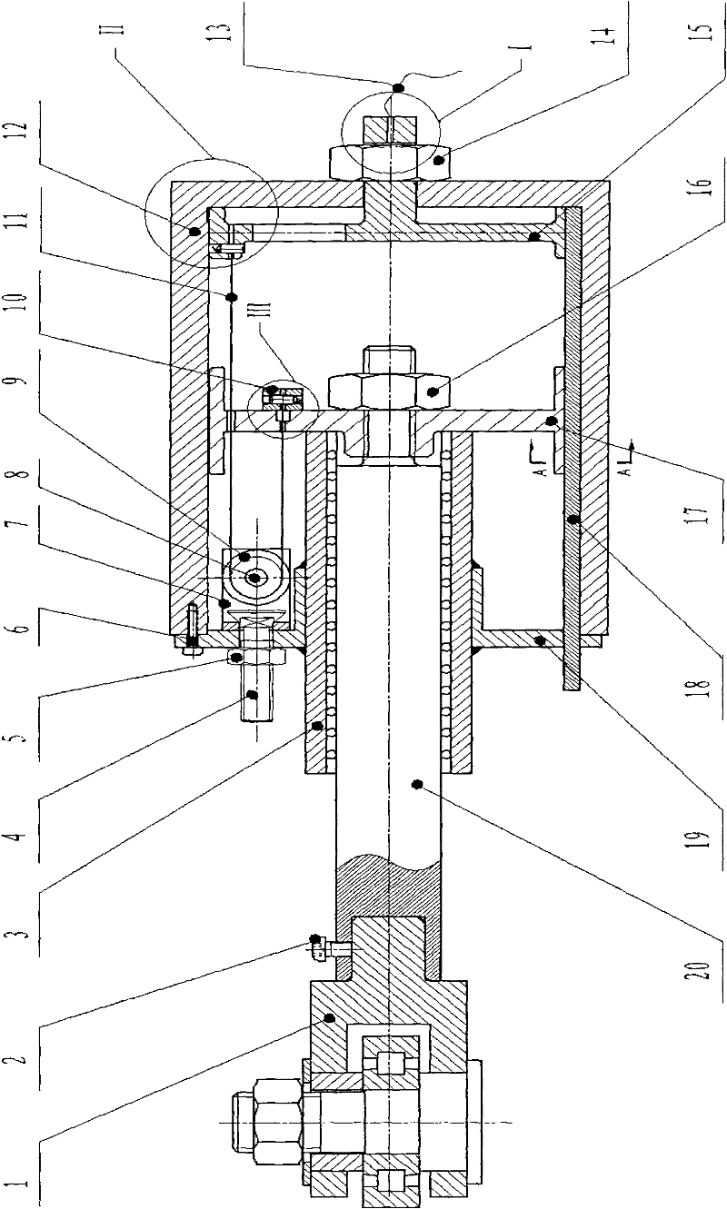
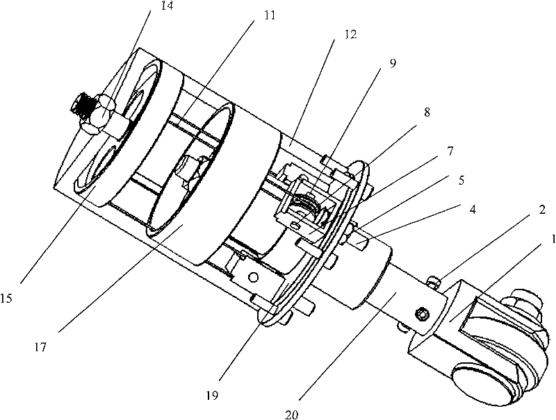
[0032] A gravity-type adjustable rolling tool is composed of a gravity reversing mechanism, a gravity traction mechanism and a roller-type rolling head.
[0033] Depend on figure 1 , 2 It can be seen that the gravity reversing mechanism is composed of three sets of fixed pulleys fixed on the end cover with square hole screws. The connection relationship is as follows: the three pulley frames 7 are fixed at intervals of 120 degrees along the circumferential direction of the end cover 18 through three square hole screws 4 and three nuts 5; Form three groups of fixed pulley mechanisms fixed on the end cover, and the direction of force can be changed by matching the three groups of fixed pulley mechanisms with the traction rope 11.
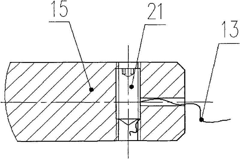
[0034] The gravity traction mechanism is composed of a heavy object suspension rope 13, a safety nut 14, a gravity traction ring 15, a traction rope 11, a sleeve 12, a thrust ring 17, a tra...
Embodiment 2
[0039] In this embodiment, on the basis of Embodiment 1, the roller-type rolling head is replaced with a ball-type rolling head, and the ball-type rolling head is fixed on the rolling shaft by three hexagon socket head cap screws 2 with a circumferential distance of 120 degrees. 20 on. The structure diagram of the ball rolling head is as follows: Figure 9 As shown, the ball rolling head is made up of a ball rolling head seat 36, a screw 37, a retaining cap 38, a small ball 39, a large ball 40, a rubber gasket 41 and a spring washer 42. Its connection form is as follows: Figure 10 As shown, a circle of small balls is installed along the bottom periphery of the stepped hole of the ball-type rolling head seat 36, and a large ball 40 is placed on the small ball. The stepped holes are equipped with rubber gaskets 41 and spring gaskets 42 in sequence. Install retaining cap 38 outside small ball 39, rubber washer 41 and spring washer 42, and be that retaining cap 38 is fixed on ...
PUM
 Abstract
Description
Claims
Application Information
 - R&D Engineer
- R&D Manager
- IP Professional
- Industry Leading Data Capabilities
- Powerful AI technology
- Patent DNA Extraction
Browse by: Latest US Patents, China's latest patents, Technical Efficacy Thesaurus, Application Domain, Technology Topic, Popular Technical Reports.
© 2024 PatSnap. All rights reserved.Legal|Privacy policy|Modern Slavery Act Transparency Statement|Sitemap|About US| Contact US: help@patsnap.com


