
LED streetlamp reflector and streetlamp having LED streetlamp reflector

A technology of LED street lights and reflectors, applied in the direction of light source, reflector, point light source, etc., can solve the problems of waste, reduce the uniformity index, and the light strip cannot be connected, and prevent movement, ensure the uniformity of brightness, darkness and brightness. The effect of reducing the spotlight phenomenon

Inactive Publication Date: 2010-07-07
ZHEJIANG JINGRI LIGHTING TECH
View PDF0 Cites 10 Cited by
  • Summary
  • Abstract
  • Description
  • Claims
  • Application Information

AI Technical Summary

Problems solved by technology

In the prior art, most of the LED street lamps that use lenses to concentrate light have a circular lighting area, and the light bands formed by two adjacent street lamps cannot be connected, resulting in dark areas on the road, which greatly reduces the uniformity. In the width direction of the road, there are a large number of invalid lighting ranges on the two edges of the circular lighting area, resulting in waste

Method used


Image

  • LED streetlamp reflector and streetlamp having LED streetlamp reflector
  • LED streetlamp reflector and streetlamp having LED streetlamp reflector
  • LED streetlamp reflector and streetlamp having LED streetlamp reflector

Examples


Embodiment 1

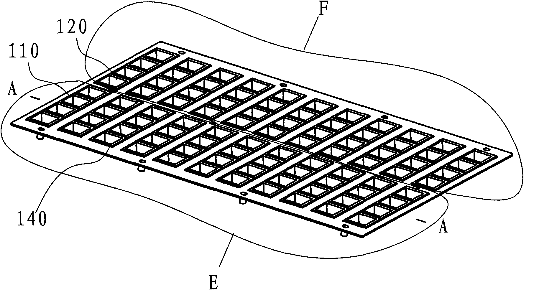
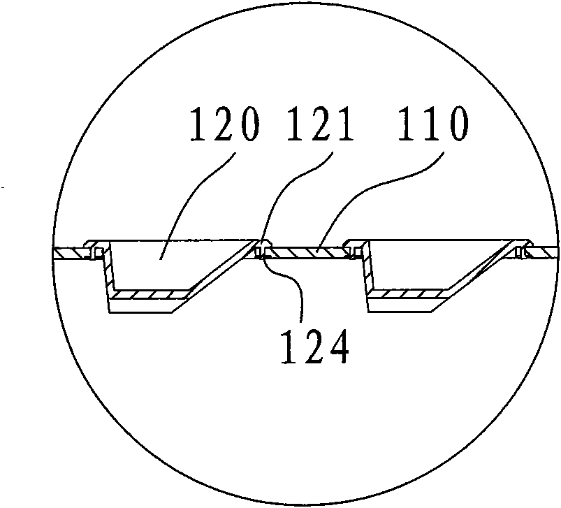
[0056] Embodiment 1: as figure 1 As shown, a reflector for LED street lamps includes a base plate 110, the base plate 110 is divided into left and right areas, and the two areas are symmetrically distributed. As shown, only the left region E is detailed. In the left area E, there are 11 base holes 118 opened in parallel, and each base hole 118 is connected with a reflector module 140 opening to the left direction, such as Figure 5 , 6 , 7, the reflective cup module 140 is composed of four reflective cups 120 arranged side by side. The opening directions of the reflector cups 120 of the reflector cup module 140 in the left area E are the same and face to the left. Each reflector cup 120 covers a light-emitting diode. shoot out in the direction of the opening. Correspondingly, the opening direction of all the reflective cups in the right area F is to the right. Therefore, the light emitted from the left and right regions of the substrate 110 is respectively emitted to the ...

Embodiment 2

[0059] Embodiment 2: as Figure 8-13 As shown, a reflective plate for LED street lamps, which includes two areas, each area is provided with 12 base holes, the base holes are used to install reflective cups 120, and the opening directions of the reflective cups 120 in the two areas are different. The middle line of the zone is perpendicular to the direction of the road, and the reflective cups 120 in the two zones respectively reflect the light emitted by the light-emitting diodes in the reflective cups forward and backward along the direction of the road. Figure 10 It is a cross-sectional view of the reflector 120 along the direction of the road, which reflects the reflected light line diagram of the reflector along the direction of the road. As shown in the figure, the light of the light-emitting diode 230 is reflected by the inner transverse surface 123 and the outer transverse surface 127 On the road, the above-mentioned two sides will control the length and uniformity of...


PUM


Abstract

The invention relates to the technical field of LED streetlamps, in particular to an LED reflector and the structure of a streetlamp having the LED lamp reflector. The LED lamp reflector comprises a substrate, wherein the substrate is provided with a plurality of reflectors which are separated into two groups according to opening directions, the opening directions of a reflector group in one group of the reflectors are the same and the opening directions of the different reflector groups are opposite in the road direction; and each reflector group at least comprises one reflector. A light band with uniform brightness and less light loss can be formed on the road according to the invention.

Description

technical field [0001] The invention relates to an LED lamp, in particular to a reflector for an LED lamp and the structure of a street lamp thereof. Background technique [0002] High-power LED (referring to a single LED power not less than 1W) lighting is a revolutionary technology recognized around the world to replace traditional lighting. High-power LED lamps can be used as replacement products for current high-power street lamps and floodlights. [0003] When LEDs are used as street lamps, due to the small lighting angle of LED particles, the uneven irradiation surface of the light causes the road surface to be dark or the light utilization rate to be low. The best lighting range of street lights is a rectangular light strip, the long side of the rectangular light strip is in line with the direction of the road, and the short side is in line with the width of the road. In the prior art, most of the LED street lamps that use lenses to concentrate light have a circular ...

Claims


Application Information

Patent Timeline
Patent Type & Authority Applications(China)
IPC IPC(8): F21V7/04F21V7/10F21Y101/02F21W131/103
CPCY02B20/72
Inventor 程世友
Owner ZHEJIANG JINGRI LIGHTING TECH
Learn More