
Data collecting device based on DCPLC mode

A data acquisition and data exchange technology, applied in data exchange network, digital transmission system, signal transmission system, etc., can solve problems such as difficulty in meeting the needs of home intelligent meter reading system, low power supply of connected equipment, and complex bus isolation device. , to achieve the effect of saving wiring costs, convenient networking, and reliable communication

Inactive Publication Date: 2010-06-30
SHANGHAI XIELIN ELECTRONICS
View PDF0 Cites 6 Cited by
  • Summary
  • Abstract
  • Description
  • Claims
  • Application Information

AI Technical Summary

Problems solved by technology

[0004] At present, the communication methods used in the existing home intelligent meter reading system mainly include the following types: based on RS485 bus, wireless RF communication and M-BUS; Solve the power supply problem alone, and can only use serial wiring to cause great difficulty for the actual wiring design and construction of the community. Failure to follow the serial wiring rules will greatly reduce the stability of communication; based on wireless RF communication methods that are affected by surrounding obstacles To a large extent, such as the complex electromagnetic environment of high-rise buildings or the space for meter installation, etc., it is a considerable test for wireless transmission technology. In addition, the wireless module needs power supply, so it is necessary to install a battery for the wireless module. The life of the wireless communication has become the bottleneck of the wireless communication; based on the M-BUS method, the communication is reliable and the anti-interference is strong. It has been widely used in various remote meter reading instruments, but there are still devices with low power supply and bus isolation device. Complicated and other disadvantages
[0005] Obviously, the above-mentioned existing methods all have their shortcomings more or less, and it is difficult to meet the needs of the existing home smart meter reading system

Method used


Image

  • Data collecting device based on DCPLC mode
  • Data collecting device based on DCPLC mode
  • Data collecting device based on DCPLC mode

Examples


Embodiment Construction

[0029] In order to make the technical means, creative features, goals and effects achieved by the present invention easy to understand, the present invention will be further described below in conjunction with specific illustrations.

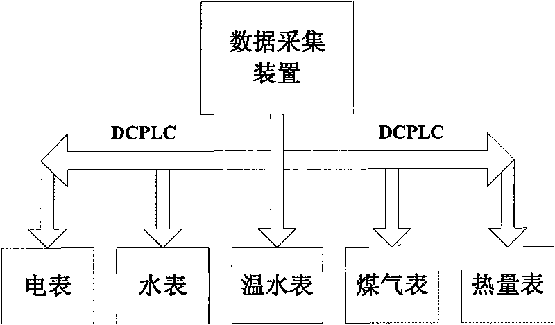
[0030] like figure 1 , figure 2 Shown, a kind of data acquisition device based on DCPLC mode, it comprises the housing of device, described data acquisition device is connected with meter (electricity meter, water meter, warm water meter, gas meter and heat meter etc.) through DCPLC mode and collects meter ( Electricity meter, water meter, warm water meter, gas meter and heat meter, etc.). (see figure 1 )

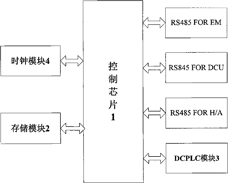
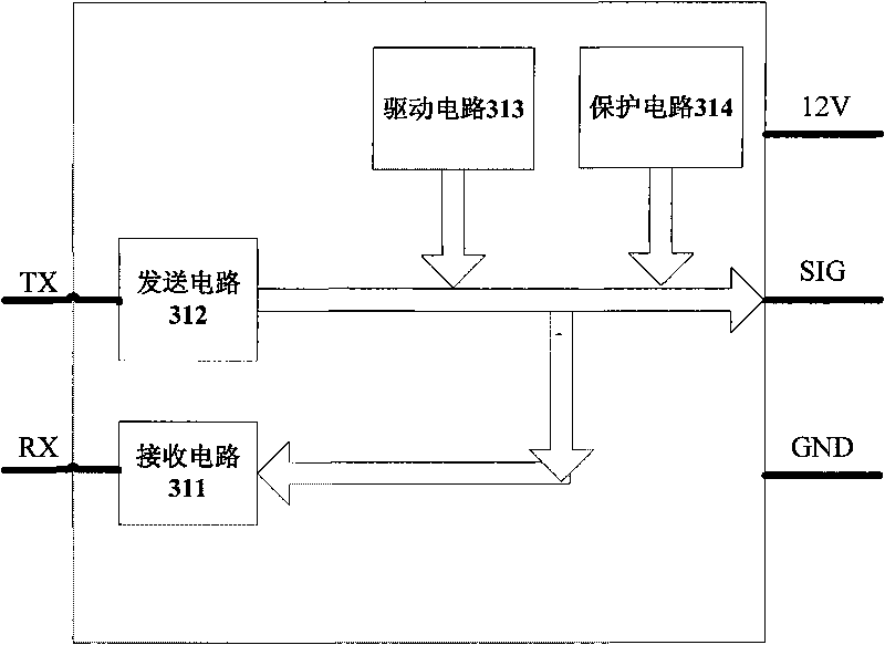
[0031] see figure 2 , the data acquisition device includes a control chip 1, a storage module 2, a DCPLC module 3 and a clock module 4, the storage module 2 is used to store instructions and data of the control chip 1, and the clock module 4 generates a corresponding clock signal to make the control chip 1 normal To work, the instructi...


PUM


Abstract

The invention aims at disclosing a data collecting device based on a DCPLC mode. The device comprises a shell, the data collecting device is connected with a meter in the DCPLC mode, the data collecting device comprises a control chip, a storing module, a DCPLC module and a clock module, and the storing module, the clock module and the DCPLC module are respectively connected with the control chip; the data collecting device based on the DCPLC mode adopts the DCPLC communication mode to collect and transmit data, when communication is not carried out, the bus level is about 11.5V, and power can be supplied to the connected meter; when the data collecting device gives instructions, the communication is carried out by the bus, the connected meter transmits the data to and fro according to addresses after receiving the instructions, thus having double functions of communication and supplying power to the meter; and a communication module of the data collecting device can realize remote metering, thus achieving the aim of the invention.

Description

technical field [0001] The invention relates to a data acquisition device, in particular to a data acquisition device based on a DCPLC method for collecting cold water meters, hot water meters, gas meters, electric meters, etc. in a household intelligent meter reading system. Background technique [0002] At present, the existing methods in our country are to install cold water meters, hot water meters, gas meters, electric meters and other meters in the user's room. Every month, the meter reading personnel must go to the user's room to read the meter and charge, which brings a lot of trouble to the user. , It also brings troubles to the meter reading personnel, causes many unnecessary disputes and has potential safety hazards. [0003] In order to effectively solve the many disadvantages of meter reading personnel entering the user's indoor meter reading charge, improve efficiency, avoid unsafe factors caused by entering the user's indoor meter reading (such as meter readin...

Claims


Application Information

Patent Timeline
IPC IPC(8): G08C19/00H04L12/00
Inventor 周育峰周峋徐峰
Owner SHANGHAI XIELIN ELECTRONICS
Learn More