
Supporting structure of beam type conversion layer template and method for strengthening substructure

A technology of formwork support and beam conversion, which is applied in the direction of building construction, formwork/formwork/work frame, and on-site preparation of building components, which can solve the unclear stress situation of support poles and increase the safety risk of support systems , The impact of the lower floor is not fully considered to achieve the effect of improving the quality of the project, enhancing the bearing capacity, and speeding up the construction speed

Inactive Publication Date: 2010-06-30
青建集团股份公司
View PDF4 Cites 20 Cited by
  • Summary
  • Abstract
  • Description
  • Claims
  • Application Information

AI Technical Summary

Problems solved by technology

There are the following problems in the construction of ordinary support systems: 1. The support system cannot withstand large loads
2. The stress of each support pole in the support system is not clear, which is not conducive to making targeted analysis and measures, and increases the safety risk of the support system
3. The impact of the entire support system, structure and construction load on the lower floor is not fully considered

Method used


Image

  • Supporting structure of beam type conversion layer template and method for strengthening substructure
  • Supporting structure of beam type conversion layer template and method for strengthening substructure
  • Supporting structure of beam type conversion layer template and method for strengthening substructure

Examples


Embodiment 1

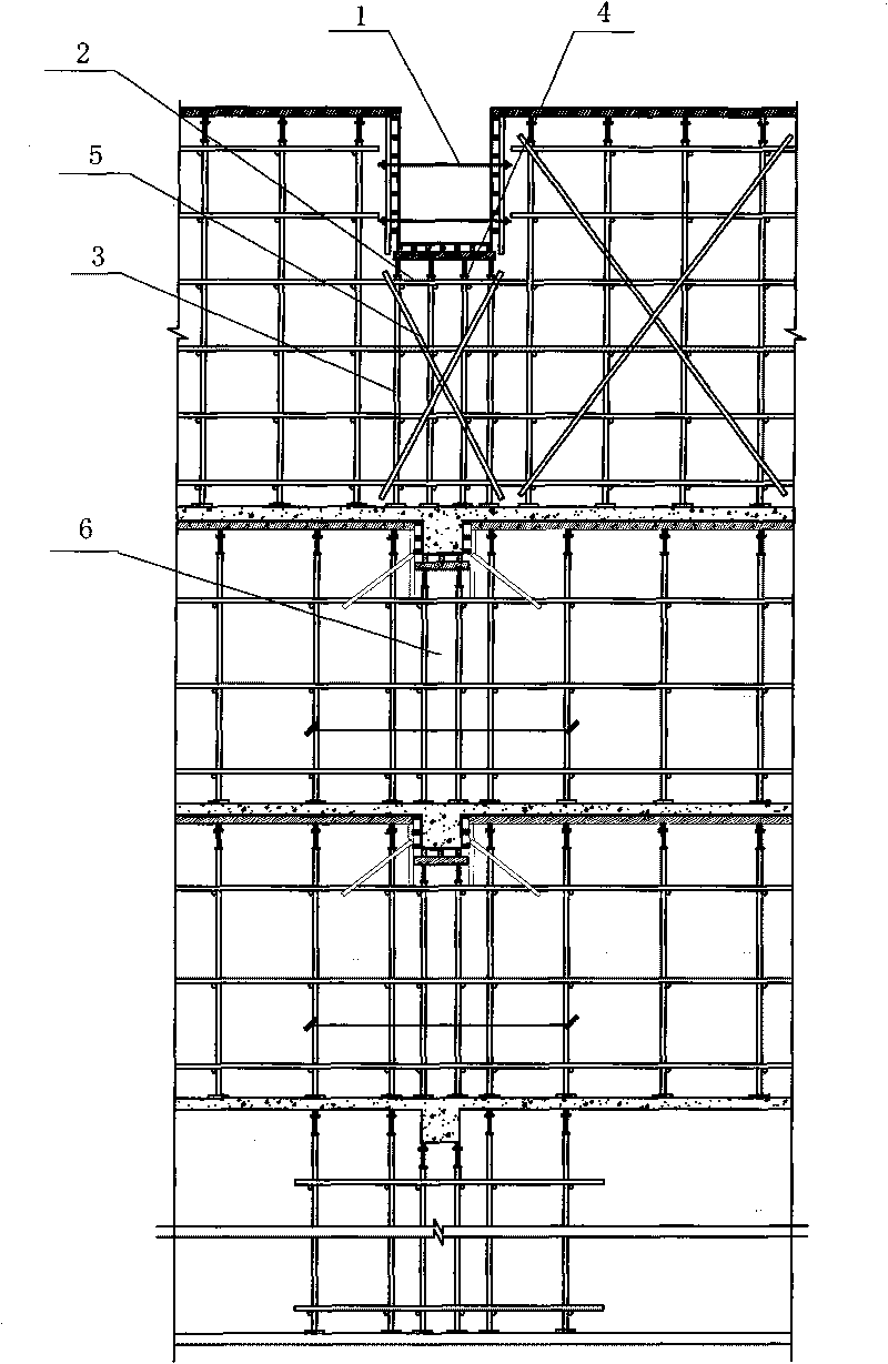
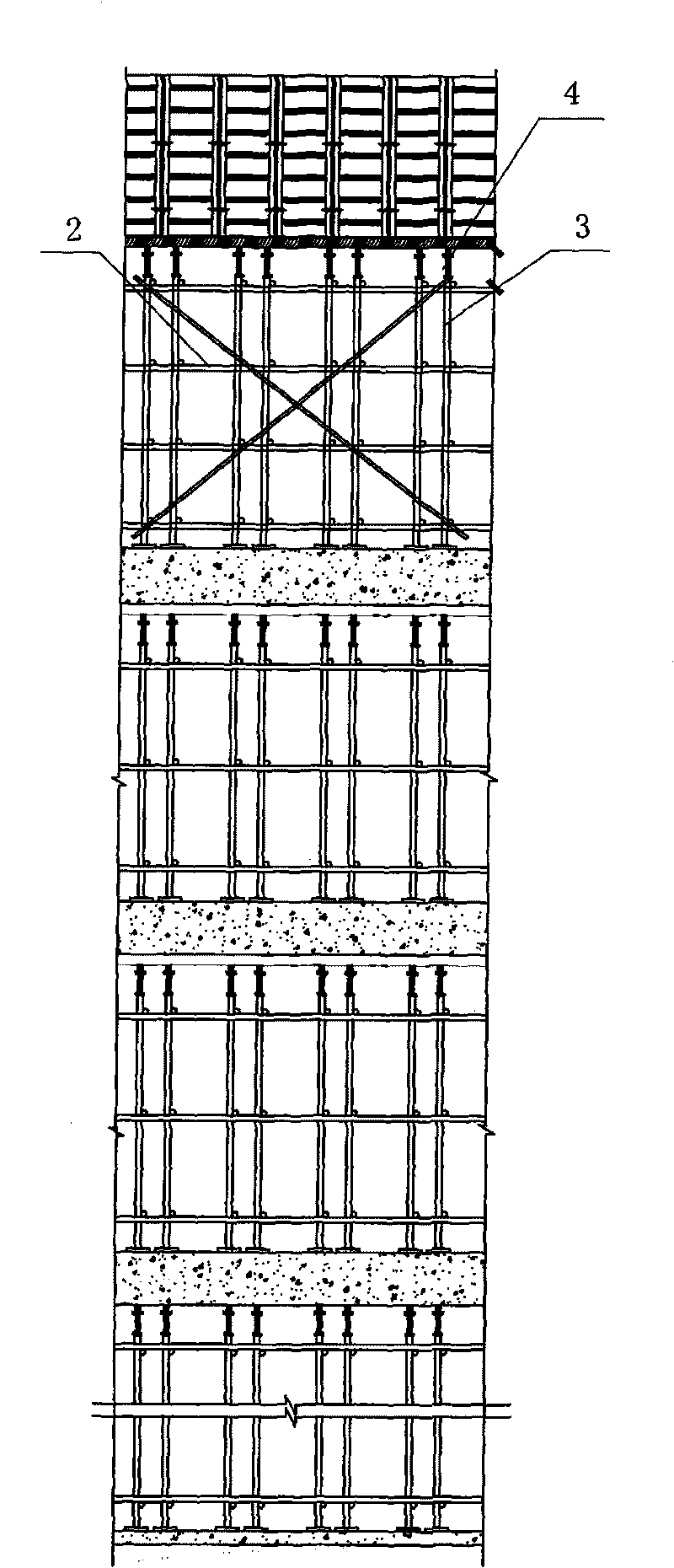
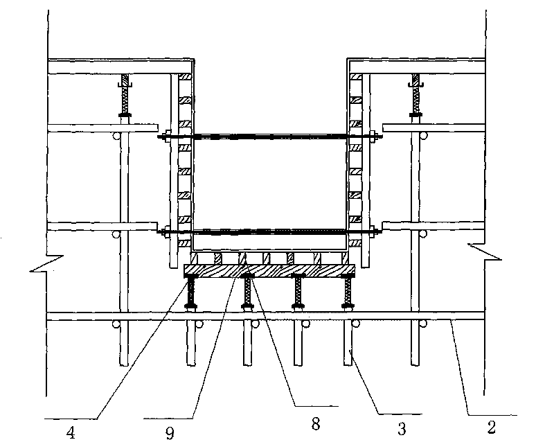
[0019] Such as figure 1 , 2 , 3, a beam-type conversion layer formwork support structure, under the beam bottom formwork 1, vertical bars 3 and cross bars 2 that are fixedly connected together are also independently arranged under the beam bottom formwork 1, and the vertical bars 3 The top is provided with an adjustable jacking 4, and between the adjustable jacking 4 and the beam bottom formwork 1, a wooden main flute 9 and a wooden second flute 8 are arranged. Bottom formwork 1 contacts, and the wooden square main flute 9 is positioned on the vertical bar 3, contacts with adjustable top bracket 4.

[0020] The vertical rods 3 are evenly distributed under the beam bottom template 1, and cross bars 5 are arranged between the vertical rods 3; the cross rods 5 are crossed in pairs, and the two ends of each cross rod 5 are respectively connected to the two farthest relative positions. The pole top and the pole bottom of root pole 3.

[0021] The specific arrangement is as follo...

Embodiment 2

[0025] Such as figure 1 , 2 As shown, a method for strengthening the lower structure of the beam-type transfer floor formwork support, which encrypts the lower floor support corresponding to the frame support beam support, and the encryption range 6 is within 800mm of the frame support beam and both sides; 2 The formwork support of the first floor is also reinforced at the position corresponding to the conversion floor beam on the next floor.

[0026] Removal of the above-mentioned support reinforcement: When the solid concrete strength of the mass concrete transfer beam reaches 100%, all the supports of the corresponding positions at the lower part of the transfer beam can be removed except the transfer layer. The corresponding formwork support can be dismantled after the concrete strength reaches the requirement in other beam and slab parts of the transfer floor.


PUM


Abstract

The invention relates to a supporting structure of a beam type conversion layer template, which is characterized in that an upright stanchion and a cross bar which are fixedly connected together are arranged independently under a beam bottom template and within a location sideline range of a beam, wherein the top end of the upright stanchion is provided with an adjustable jacking, and a wood beam is arranged between the adjustable jacking and the beam bottom template. The invention also discloses a method for strengthening a substructure of the supporting structure of the beam type conversion layer template. The invention utilizes the upright stanchion arranged independently under a frame-supported beam to bear greater load; the upright stanchion arranged independently under the beam can carry out a loading analysis precisely, which is favorable for adopting a targeted strengthening measure; and strengthening on a lower floor can avoid structural quality accident caused by the great load of the conversion layer.

Description

technical field [0001] The invention relates to a formwork supporting structure of a beam-type transfer floor, and in particular to a method for reinforcing its substructure. It belongs to the technical field of construction engineering. Background technique [0002] Modern high-rise buildings are developing towards multi-functional and comprehensive purposes. On the same vertical line, the top floors are arranged with residences and hotels, the middle floors are used as office rooms, and the lower floors are used as shops, restaurants and cultural and entertainment facilities. Floors with different uses require bays of different sizes and adopt different structural forms. This requires the top of the building to be the axis of the small bays and arrange more walls, the middle part should have small and medium-sized interior spaces, and the lower part should have as much free and flexible space as possible, the column network should be large, and the walls should be as few ...

Claims


Application Information

Patent Timeline
IPC IPC(8): E04G11/50
Inventor 连健张同波
Owner 青建集团股份公司
Learn More