
Fiber laser adopting end face coated cavity mirror

A fiber laser and coating cavity technology, applied in the direction of lasers, laser components, phonon exciters, etc., can solve problems affecting performance, grating ablation, and vulnerability to damage, and achieve long service life, not easy to aging, and anti-damage The effect of high threshold

Inactive Publication Date: 2013-04-03
WUXI RES INST OF APPLIED TECH TSINGHUA UNIV +1
View PDF0 Cites 0 Cited by
  • Summary
  • Abstract
  • Description
  • Claims
  • Application Information

AI Technical Summary

Problems solved by technology

For the first method, if it is used for high-power fiber lasers, since the gain fibers are double-clad fibers, the outer cladding is generally made of polymer materials, which are easily damaged during the hydrogen-loaded sensitization process, which seriously affects the pumping light. Coupling, resulting in low coupling efficiency. At the same time, the polymer outer cladding material is generally opaque to ultraviolet light, which also brings difficulties to the production of fiber gratings.
For the second method, after splicing the grating-written non-gain fiber to the double-clad gain fiber, there will be splice loss
Moreover, in high-power lasers, the strong light beam will cause certain damage to the grating, which will change the refractive index of the grating and affect its performance; in severe cases, the grating will be ablated and make it invalid

Method used


Image

  • Fiber laser adopting end face coated cavity mirror
  • Fiber laser adopting end face coated cavity mirror
  • Fiber laser adopting end face coated cavity mirror

Examples


Embodiment 1

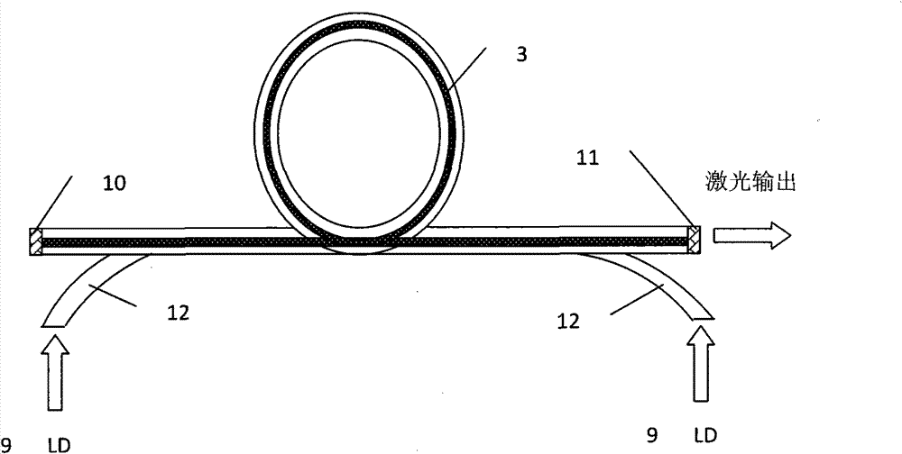
[0028] Such as figure 2 As shown, this example is an embodiment of a coated cavity mirror used in a side-pumped fiber laser. Semiconductor laser pumping source (9), optical coating layer (10), (11) and gain fiber (3) form basic Fabry-Perot resonant cavity, optical coating layer (10), (11) at fiber two ends as cavity mirror . The coated cavity mirrors (10), (11) are formed by coating a section of the gain fiber (3) with a thin film on the end face. The coated cavity mirror (10) at the left end is highly reflective to the fiber laser; the coated cavity mirror (11) as an output mirror is partially transparent to the fiber laser. The gain fiber (3) is formed by doping ytterbium ions with a flat top on the cross section. The pumping light is injected into the inner cladding of the gain fiber (3) from the side through the guide fiber (12), and the laser oscillation is excited in the gain fiber (3). In the laser, the laser light travels between two cavity mirrors multiple times ...

Embodiment 2

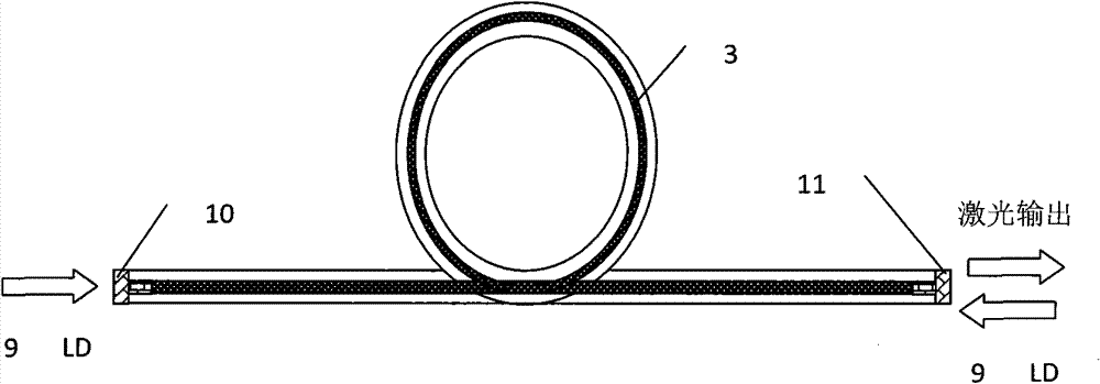
[0030] Such as image 3 As shown, this example is an embodiment of a coated cavity mirror used in an end-pumped fiber laser. The semiconductor laser pumping source (9), the coated cavity mirrors (10), (11) and the gain fiber (3) form a basic Fabry-Perot resonant cavity. The coated cavity mirrors (10) and (11) are respectively formed by coating optical thin films on the end surfaces of two small optical fibers. These two sections of small fibers are undoped fibers with the same parameters as the gain fiber (3). The coated cavity mirror (10) at the left end is antireflective to the pump wavelength and highly reflective to the laser wavelength; the coated cavity mirror (11) as an output mirror is antireflective to the pump wavelength and partially transparent to the laser wavelength. The gain fiber (3) is formed by gradual doping of germanium ions on the cross section. Pumping light is injected into the inner cladding of the gain fiber (3) from both end faces to excite laser o...


PUM


Abstract

The invention relates to a fiber laser adopting an end face coated cavity mirror. The fiber laser is characterized by comprising the coated cavity mirror, a pumping device and a doped fiber serving as a gain medium, wherein the coated cavity mirror is a fiber end face thin film with a certain optical characteristic which is formed by coating a film on the end face of a small section of fiber; andthe small section of fiber is a section of gain fiber or a section of undoped fiber which has the same parameter as the gain fiber. The end face coating film is adopted by the fiber laser as a cavitymirror, so that the service life and the damage threshold of the cavity mirror are improved; and consequently, the cavity mirror cannot be ablated or damaged when working at a higher power.

Description

technical field [0001] The invention relates to a fiber laser, in particular to a fiber laser using an end-face coated cavity mirror. Background technique [0002] Because of its excellent beam quality, very high power and power density, easy cooling, high stability and reliability, fiber lasers have attracted increasing attention and have been widely used in many fields. In fiber lasers, Fabry-Perot cavities are generally used as resonant cavities. The cavity mirror of the Fabry-Perot cavity has many different forms: placing a dichroic mirror before and after the fiber, coating the fiber end face, writing the fiber grating into the gain or non-gain fiber, etc. In the article "Spectral profile and multiplexing of Bragg gratings in photosensitive fiber" (OPTICS LETTERS, Vol.16, No.12, 1991), R.J.Campbell and R.Kashyap first proposed the method of using fiber gratings for fiber lasers. Since then, fiber gratings have been widely used in the design and manufacture of fiber la...

Claims


Application Information

Patent Timeline
Patent Type & Authority Patents(China)
IPC IPC(8): H01S3/067H01S3/08H01S3/06H01S3/0941
Inventor 巩马理闫平张海涛郝金坪廖素英
Owner WUXI RES INST OF APPLIED TECH TSINGHUA UNIV
Learn More