
Multi-axis capacitive accelerometer

An accelerometer, capacitive technology, applied in the design field of multi-axis capacitive accelerometer, can solve the problem of reducing the effective area utilization rate and so on

Active Publication Date: 2010-06-16
IND TECH RES INST
View PDF2 Cites 53 Cited by
  • Summary
  • Abstract
  • Description
  • Claims
  • Application Information

AI Technical Summary

Problems solved by technology

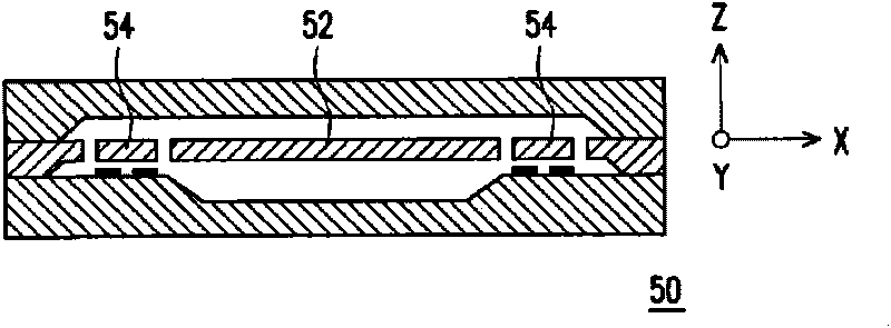
Generally speaking, for the design of a three-axis integrated accelerometer, when the Z-axis torsion structure is designed within the XY-axis structure, because the symmetry of the XY-axis structure mass must be considered, its rotation axis will be symmetrically placed at the center of the XY-axis structure , so that the effective area utilization rate of the lighter side of the mass block is reduced; in addition, when the Z-axis torsion structure is designed within the XY-axis structure, if the manufacturing method is to use two electrodes on another substrate to form a differential capacitance with the structure , although the Z-axis capacitance of this design is very low affected by its axial force, but in order to achieve mass symmetry, it will also cause it to use a part of the area only for mass balance and cannot contribute to sensing purposes, and The design using two sets of torsion structures can naturally form symmetry without forcing the rotation axis to be placed at the center of the XY axis structural mass, which can achieve the purpose of improving the area utilization efficiency and reducing the other axis sensitivity of the Z axis

Method used


Image

  • Multi-axis capacitive accelerometer
  • Multi-axis capacitive accelerometer
  • Multi-axis capacitive accelerometer

Examples


Embodiment Construction

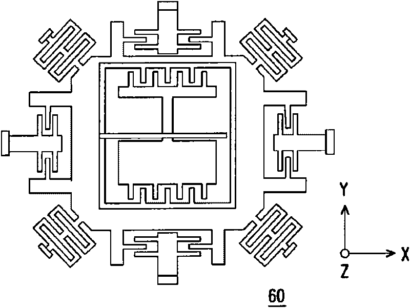
[0105] Figure 4 It is a top view of a multi-axis capacitive accelerometer according to an embodiment of the present invention. Figure 5 for Figure 4 Sectional view along line I-I. Please refer to Figure 4 and Figure 5 , the multi-axis capacitive accelerometer 1000 of this embodiment includes a substrate 1100 and a structural layer 1200 . A plurality of sensing electrodes 1120 are disposed on the surface 1110 of the substrate 1100 . The structural layer 1200 includes a plurality of fixed seats 1210, a first mass 1220, a first elastic structure 1230, a plurality of fixed sensing masses 1240, a second mass 1250, a third mass 1260, a second elastic structure 1270 and a third mass. Elastic structure 1280.

[0106] The first mass 1220 is disposed above the surface 1110 of the substrate 1100 , and the first mass 1220 has a central axis 1222 and a first opening 1224 and a second opening 1226 inside the first mass 1220 . The first opening 1224 and the second opening 1226 ar...


PUM


Abstract

A multi-axis capacitive accelerometer is consisted of a substrate with sensing electrodes and a structure layer. The structure layer includes anchor bases fixed on the substrate, a movable first proof mass, a group of first flexible structures, a plurality of fixed sensing blocks, a second proof mass, a third proof mass, a second flexible structure and a third flexible structure. The first proof mass is disposed over the substrate and has a first opening and a second opening symmetric to each other. The flexible structures are connected with the anchor bases and the first proof mass. The fixed sensing blocks are disposed on the substrate, and capacitors are formed between each fixed sensing block and the first proof mass for sensing acceleration along two in-plane directions. The second proof mass and the third proof mass are disposed over the substrate and in the first opening and the second opening and are asymmetrically suspended over the first proof mass respectively by the second flexible structure and the third flexible structure. Separate electrodes are disposed on the substrate and form two differential capacitors with the second proof mass and the third proof mass for sensing the out-of-plane acceleration.

Description

technical field [0001] The present invention relates to a capacitive accelerometer, and in particular to the design of a multi-axis capacitive accelerometer. Background technique [0002] Accelerometers are currently widely used in many devices in the market as motion sensors, such as game consoles, health monitoring, mobile phone interface control and automatic mute, inertial cursor pointers and other fields. [0003] Traditional micro-electromechanical three-axis accelerometers mostly adopt a single-axis combined three-axis design, which means that the masses and sensing elements used to sense the acceleration of the X-axis, Y-axis, and Z-axis are set independently. Although this arrangement can achieve the purpose of reducing the sensitivity of its axis in acceleration sensing, its disadvantage is that in order to achieve the goal of low mechanical noise, the size of the component is often too large, or in order to achieve the goal of small size, the mechanical noise The...

Claims


Application Information

Patent Timeline
IPC IPC(8): G01P15/18G01P15/125
Inventor 许郁文陈士简欣堂
Owner IND TECH RES INST
Learn More