


Quick Research
Generate reliable direction feasibility study reports for your R&D in just a few steps.

Technical Q&A
Discover and master advanced knowledge NOW. Basics, ideas, possibilities, all at once.

Find Solutions
As an expert in R&D theories, this can generate solutions to your technical problems instantly.

Evaluate Feasibility
Analyze your overall solution with one click, know your potential R&D risks in advance.

Monitor Landscape
Get weekly tech updates, stay abreast of the latest tech innovations and key insights.
Multi-antenna measurement method and multi-antenna measurement system
A measurement method and measurement system technology, applied in diversity/multi-antenna systems, transmission systems, polarization/direction diversity, etc., can solve problems such as inability to achieve performance evaluation, and achieve the effect of simple evaluation and simple structure
- Summary
- Abstract
- Description
- Claims
- Application Information
AI Technical Summary
Problems solved by technology
Method used
Image

Examples
no. 1 Embodiment approach
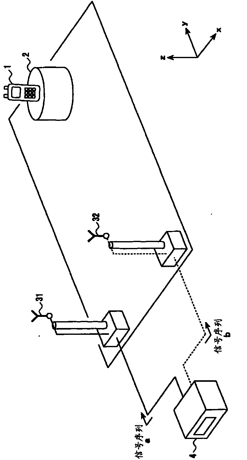
[0057] refer to figure 1 , the antenna measurement method of the first embodiment will be described. figure 1 It is a figure which shows the example of the antenna measurement system for carrying out the antenna measurement method of 1st Embodiment.
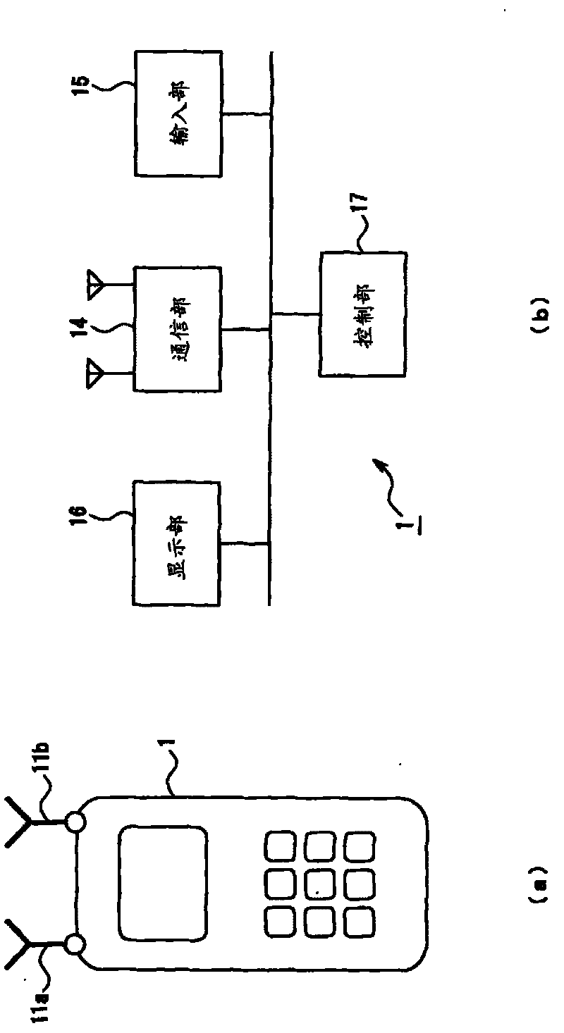
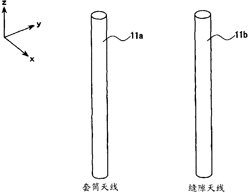
[0058] The device to be measured by the antenna measurement method of the present invention, that is, the device 1 to be measured is a mobile terminal such as a mobile phone having at least two antennas. figure 2 (a) shows an example of the external configuration of the device to be measured 1 . Such as figure 2 As shown in (a), the device under test 1 has two antennas 11a and 11b, and these constitute a multi-antenna.
[0059] also, figure 2 (b) shows an example of the internal configuration of the device to be measured 1 . Such as figure 2 As shown in (b), the device 1 to be measured has: the communication unit 14 for controlling the transmission and reception of the antennas 11a, 11b; the input unit 15 for inputtin...
no. 2 Embodiment approach
[0109] refer to Figure 17 , the antenna measurement method of the second embodiment will be described. Figure 17 It is a figure which shows the example of the antenna measurement system for carrying out the antenna measurement method of 2nd Embodiment. In this embodiment, the measurement is performed in an environment in which there are not only downlink radio waves transmitted from the transmitting antennas 31 and 32 to the device under test 1, but also signals from the device under test 1 to the simulated base station device. 4 transmitted uplink radio waves.
[0110] (Structure example 1)
[0111] here, as Figure 18 As shown, a received signal quality information generating unit 12 is provided in the device under test 1 to generate information indicating the received signal quality, that is, received signal quality information. The received signal quality information generated by the received signal quality information generation unit 12 is transmitted to the analog ...
no. 3 Embodiment approach
[0120] refer to Figure 21 The antenna measurement method of the third embodiment will be described. Figure 21 It is a figure which shows the example of the antenna measurement system for carrying out the antenna measurement method of 3rd Embodiment. In this embodiment, variable attenuators 71 and 72 and interference signal generators 81 and 82 are provided between transmitting antennas 31 and 32 and analog base station apparatus 4 in order to control the quality of the received signal of device under test 1 . The variable attenuators 71 and 72 have a function of changing the intensity of the signal output from the analog base station apparatus 4 . In addition, the interference signal generators 81, 82 have a function of changing the amount of interference included in the signals output from the transmitting antennas 31, 32. That is, in this embodiment, these variable attenuators 71, 72 and the interference signal generators 81, 82 can change the strength and interference a...
PUM
 Abstract
Description
Claims
Application Information
 - R&D Engineer
- R&D Manager
- IP Professional
- Industry Leading Data Capabilities
- Powerful AI technology
- Patent DNA Extraction
Browse by: Latest US Patents, China's latest patents, Technical Efficacy Thesaurus, Application Domain, Technology Topic, Popular Technical Reports.
© 2024 PatSnap. All rights reserved.Legal|Privacy policy|Modern Slavery Act Transparency Statement|Sitemap|About US| Contact US: help@patsnap.com