
Sea water buoyancy generating set

A power generation device and buoyancy technology, which is applied in hydroelectric power generation, ocean energy power generation, engine components, etc., can solve the problems of difficult application, large investment, slow effect, etc., and achieve the effect of less restrictive conditions and high utilization rate of seawater kinetic energy

Inactive Publication Date: 2010-06-09
蒋建新
View PDF0 Cites 6 Cited by
  • Summary
  • Abstract
  • Description
  • Claims
  • Application Information

AI Technical Summary

Problems solved by technology

Moreover, the investment is large, the effect is slow, and the application is difficult

Method used


Image

  • Sea water buoyancy generating set

Examples


Embodiment Construction

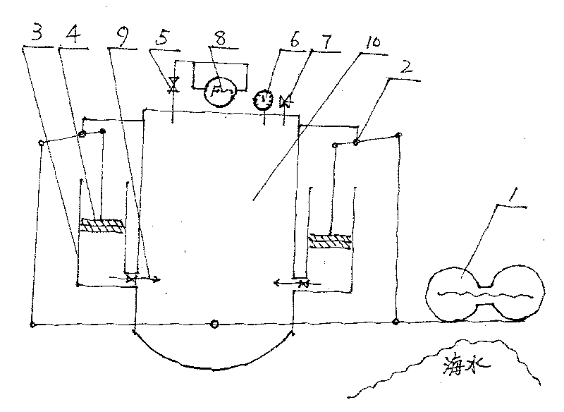
[0009] The buoyancy of the sea water is used to hold up the buoy 1 to balance the lever 2, and the swell is used to raise the buoy 1 to generate lift and drive the lever 2 to move upward. The wave valley and the pontoon 1 are used to fall under their own weight to generate downward pressure and drive the lever 2 to move downward. (According to local wave height, wave distance, sea conditions, inject appropriate amount of fresh water into the pontoon to increase the downforce) basically achieve and rise balance, so that the pontoon 1 produces continuous up and down reciprocating motion in dynamic seawater. Using the lever principle, increase the push and pull force, use the lever 2 to change the direction of force, drive the piston 4 to reciprocate in the cylinder liner 3, and continuously compress the air into the air storage tank 10 like a high-pressure air cylinder 9, through the pressure gauge 6 and The safety valve 7 controls the pressure in the gas storage tank 10 so that ...


PUM


Abstract

The invention provides a sea water buoyancy generating set, which relates to using marine resource to change the current energy structure and open a new path for generating. The invention mainly uses sea waves which are converted to a generating power by using a gas storage tank device via the lever principle, and the generating mode can play the role of energy saving and emission reducing.

Description

Technical field [0001] The invention relates to the use of marine resources to change the existing energy structure, in particular to a seawater buoyancy power generation device. Background technique [0002] At present, the use of seawater tidal power generation is limited by the total amount of seawater flowing in and out of the dike. Using the impact of ocean waves to generate electricity requires a special dam, and the impulse of sea water is discontinuous, which is limited by energy accumulation. Moreover, the investment is large, the effect is slow, and the application is difficult. Summary of the invention [0003] The purpose of the present invention is to solve the problem of using the buoyancy of sea water and the drop kinetic energy of the surge to generate electricity. [0004] The present invention is realized by using the buoyancy of sea water to lift the pontoon to balance the lever, and use the surge to raise the pontoon to generate lift and drive the lever to move...

Claims


Application Information

Patent Timeline
Patent Type & Authority Applications(China)
IPC IPC(8): F03B13/14F03B17/02
CPCY02E10/38Y02E10/20Y02E10/30
Inventor 蒋建新
Owner 蒋建新
Learn More