
Petroleum mixing and conveying pump

A technology of conveying pump and oil, applied in the field of oil mixing conveying pump, can solve the problems of high load and slow conveying of conveying pump, and achieve the effect of high conveying rate, low local flow resistance and improving kinetic energy utilization rate.

Inactive Publication Date: 2017-07-21
YANCHENG JINRUI PETROLEUM MACHINERY CO LTD
View PDF0 Cites 1 Cited by
  • Summary
  • Abstract
  • Description
  • Claims
  • Application Information

AI Technical Summary

Problems solved by technology

[0002] Due to the different conditions in the oil field, oil with different viscosities may be produced at the same location in different time periods. If the oil with lower viscosity is transported at a faster rate, the load on the transport pump will be low, while for oil with higher viscosity, the transport will be slower. The load on the delivery pump is relatively high. If it is directly mixed and delivered, the low-viscosity oil will lose the advantage of low-viscosity fluidity, and because of the temperature drop during the delivery process, after the high- and low-viscosity oils are mixed, the delivery Rates comparable to those delivered by high-viscosity petroleum alone

Method used


Image

  • Petroleum mixing and conveying pump

Examples


Embodiment Construction

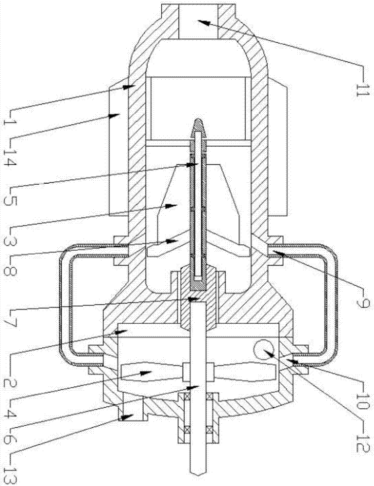
[0018] The present invention is described in further detail now in conjunction with accompanying drawing. These drawings are all simplified schematic diagrams, which only illustrate the basic structure of the present invention in a schematic manner, so they only show the configurations related to the present invention.

[0019] Such as figure 1 As shown, the present invention is a kind of oil mixing delivery pump, comprising a pump casing body, the pump casing body is divided into an inlet chamber and a driving chamber, and the inlet chamber and the driving chamber are coaxially fixedly connected; The cavity is a gradually expanding tube structure, the constricted end of the inlet cavity is provided with a feed port, the flared end of the inlet cavity is a closed structure, and the tail of the inlet cavity is connected to a pressure impeller with a conical platform structure, and the pressure The impeller includes a support block, on which a number of driving blades are arran...


PUM


Abstract

The invention relates to a petroleum mixing and conveying pump. The pump casing body is divided into an inflow cavity and a driving cavity; the constricted end of the inflow cavity is provided with a feeding port; A pressure impeller with a conical table structure is rotatably connected to the tail, and the pressure impeller includes a support block. A number of driving blades coplanar with the axis of the support block are arranged in an array on the support block. A plurality of discharge nozzles are arranged in an annular array on the inner wall of the inflow cavity corresponding to the distribution plate. A centrifugal impeller is rotatably connected in the driving cavity. The centrifugal impeller includes a rotating block. The annular array is provided with a number of centrifugal blades on the rotating block. The centrifugal impeller The support block and the rotating block of the pressure impeller are coaxially rotated and fixed, and a number of inflow nozzles are arranged in an annular array on the inner wall of the driving cavity. The inner wall is provided with a liquid inlet, and a liquid discharge port is provided at the end of the axis of the drive cavity.

Description

technical field [0001] The invention relates to a conveying pump device used for mixed driving of petroleum with different viscosities, in particular to a petroleum mixing conveying pump. Background technique [0002] Due to the different conditions in the oil field, oil with different viscosities may be produced at the same location in different time periods. If the oil with lower viscosity is transported at a faster rate, the load on the transport pump will be low, while for oil with higher viscosity, the transport will be slower. The load on the delivery pump is relatively high. If it is directly mixed and delivered, the low-viscosity oil will lose the advantage of low-viscosity fluidity, and because of the temperature drop during the delivery process, after the high- and low-viscosity oils are mixed, the delivery The rate is comparable to that delivered by high viscosity oil alone. Contents of the invention [0003] The technical problem to be solved by the present in...

Claims


Application Information

Patent Timeline
Patent Type & Authority Applications(China)
IPC IPC(8): F04D7/04F04D13/04F04D29/42F04D29/44F04D29/22F04D29/58
CPCF04D7/04F04D13/021F04D13/04F04D29/185F04D29/2238F04D29/4273F04D29/4293F04D29/445F04D29/586
Inventor 花金年钱瑞祥钱正楠
Owner YANCHENG JINRUI PETROLEUM MACHINERY CO LTD
Learn More