Automatic lifting flagpole

An automatic lifting and flagpole technology, applied in the direction of flags/flags, instruments, display devices, etc., can solve the problems of time-consuming, unable to lower the flag, cumbersome operation of the flag raising device, etc., and achieve the effect of high kinetic energy utilization rate and high degree of integration

Active Publication Date: 2019-12-20
鲜明旗帜(北京)有限公司
View PDF7 Cites 1 Cited by
  • Summary
  • Abstract
  • Description
  • Claims
  • Application Information

AI Technical Summary

Problems solved by technology

[0002] We can see some high-flying flags everywhere in our life. Many schools and enterprises will raise the national flag and private flags symbolizing their own schools or enterprises in iconic places. The high-flying flags represent the precious qualities of enthusiasm and hard work. However, it is not possible for every company to protect the flag from rain damage according to the weather conditions in life, because few people often pay attention to the state of the flag. The flag raising devices on the market are pulleys and manually controlled lifting, but people cannot The flag is lowered in bad weather. At the same time, the flag raising device that needs to be controlled by people is cumbersome and time-consuming. Therefore, it is necessary to design an automatic lifting flagpole to solve the above problems

Method used


Image

  • Automatic lifting flagpole
  • Automatic lifting flagpole
  • Automatic lifting flagpole

Examples


Embodiment Construction

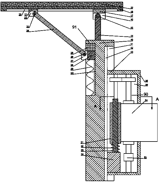
[0016] Combine below Figure 1-4 The present invention is described in detail, and for convenience of description, the orientations mentioned below are now stipulated as follows: figure 1 The up, down, left, right, front and back directions of the projection relationship itself are the same.

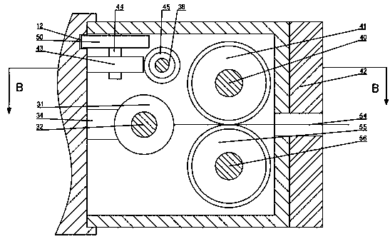
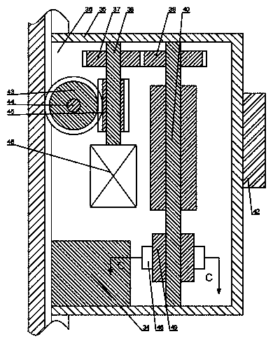
[0017] combined with Figure 1-4 The described automatic lifting flagpole comprises a flagpole 10, the right side of the flagpole 10 is fixedly provided with a first chute 11, the first chute 11 contains a first slider 35, and the first slider 35 It contains a storage cavity 36, which contains a control mechanism 90 for unfolding or storing the flag, a motor 46 is fixed on the rear end wall of the storage cavity 36, and a motor 46 is fixed on the left end surface of the first chute 11. The rack 12, the top surface of the motor 46 is rotated with a first rotating shaft 38, the first rotating shaft 38 is fixed with a worm 45, and the rear end wall on the left side of the storage chamber ...


PUM


Abstract

The invention discloses an automatic lifting flagpole. The automatic lifting flagpole comprises a flagpole body, a first sliding groove is fixedly formed in one side of the flagpole body, and a firstsliding block is contained in the first sliding groove. A storage cavity is formed in the first sliding block, and a control mechanism for unfolding or storing a flag is contained in the storage cavity. A motor is fixedly arranged on the rear end wall in the storage cavity, and a rack is fixed to the left end face of the first sliding groove. A first rotary shaft is rotationally arranged on the top end face of the motor. According to the automatic lifting flagpole, the flag raising sliding block is driven to the top end of the flagpole body through the cooperation of a gear and the rack, the stored flag is unfolded in the rising process of the flag raising sliding block, and the process is high in integration degree and high in kinetic energy utilization rate. A solar panel is arranged atthe top end of the flagpole body and can detect the weather situation, the equipment is protected in real time, and the solar panel provides power for the motor; and the equipment is used without manual intervention, is overall safe and environment-friendly, and is high in integration degree.

Description

technical field [0001] The invention relates to the field of ceremonial articles, in particular to an automatic lifting flagpole. Background technique [0002] We can see some high-flying flags everywhere in our life. Many schools and enterprises will raise the national flag and private flags symbolizing their own schools or enterprises in iconic places. The high-flying flags represent the precious qualities of enthusiasm and hard work. However, it is not possible for every company to protect the flag from rain damage according to the weather conditions in life, because few people often pay attention to the state of the flag. The flag raising devices on the market are pulleys and manually controlled lifting, but people cannot The flag is lowered under bad weather conditions. At the same time, the operation of the flag-raising device controlled by people is tedious and time-consuming. Therefore, it is necessary to design an automatic lifting flagpole to solve the above proble...

Claims


Application Information

Patent Timeline
Patent Type & Authority Applications(China)
IPC IPC(8): E04H12/32G09F17/00
CPCE04H12/32G09F17/00G09F2017/0025
Inventor 吴美俊
Owner 鲜明旗帜(北京)有限公司
Why Eureka
Try Eureka