Vapor collecting device

A recovery device, steam technology, applied in the direction of special distribution devices, etc., can solve the problems of unevenness, non-adsorption of gasoline vapor, etc., and achieve the effect of ensuring accuracy

Active Publication Date: 2010-06-09
MITSUBISHI ELECTRIC CORP
View PDF7 Cites 4 Cited by
  • Summary
  • Abstract
  • Description
  • Claims
  • Application Information

AI Technical Summary

Problems solved by technology

[0005] However, the amount of fuel (flow rate) to be refueled is not uniform throughout the refueling time. During refueling, the flow rate may be high or the flow rate may be throttled (low flow rate).
[0006] For example, if refueling is carried out for a long time with a high flow rate of refueling, the amount of gasoline vapor generated will also increase, and there is a stage before the adsorbent is desorbed, the adsorbent is saturated, gasoline vapor is not adsorbed, and the gasoline is desorbed. Potential for vapor release to atmosphere
[0007] On the other hand, in the case of refueling in which the flow rate of refueling is throttled for a long time, there is a problem of switching to the desorption process even if the adsorption capacity of the adsorbent is sufficient.

Method used


Image

  • Vapor collecting device
  • Vapor collecting device
  • Vapor collecting device

Examples


Embodiment Construction

[0080] Hereinafter, embodiments of the present invention will be described with reference to the drawings.

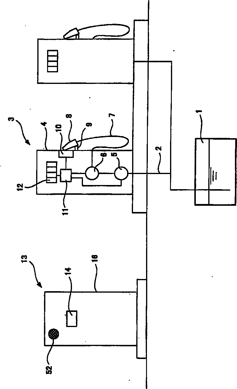
[0081] figure 1 It shows the whole of the gas station equipped with the vapor recovery device of the gas dispenser according to the present invention.

[0082] An oil storage tank 1 is buried underground in a gas station, and a filling pipe 2 connected to the oil storage tank 1 is arranged in a housing 4 of a fuel dispenser 3 .

[0083] Inside the housing 4 , a fuel pump 5 and a flow meter 6 are sandwiched between a fuel pipe 2 , and a fuel hose 7 is connected to the fuel pipe 2 .

[0084] A fuel nozzle 8 is provided at the tip of the fuel hose 7 . The fuel nozzle 8 is hung on a nozzle hanger 9 , and a nozzle switch 10 is provided on the nozzle hanger 9 . The nozzle switch 10 outputs an ON signal when the fuel nozzle leaves the nozzle hanger 9 .

[0085] The fuel dispenser 3 is provided with a fuel control unit 11 .

[0086] The refueling control unit 11 receives t...


PUM


Abstract

The invention provides a vapor collecting device which enables the absorbent to reach saturation without desorbing the absorbent with abundant absorption capability, and will not discharge the petrol vapor into the atmosphere. In the invention, a first pump (19) is mounted on the recovering pipe (15) of the filler nozzle (8) with a front end opening (17), the recovering pipe (15) passes through the concentration slot (20) and is opened in the gas-liquid separation chamber (21), the gas-liquid separation chamber (21) is in connection with the first or the second absorption tower (33, 34), the second pump is mounted on the circulation pipe (48) in connection with the first or the second absorption tower (33, 34), the circulation pipe (48) is in connection with the absorption side of the first pump (19), and the control device (14) performs switching between the absorption step and the desorption step.

Description

technical field [0001] The present invention relates to a vapor recovering device installed at a gas station for adding fuel oil to automobiles to recover gasoline vapor flowing out of the fuel tank of the automobile during refueling. Background technique [0002] Fuel oil such as gasoline is highly volatile, and when the fuel tank of an automobile is refueled, gasoline vapor flows out of the fuel tank in proportion to the amount of refueling. If this gasoline vapor is released into the atmosphere, not only will resources be wasted, but also there is a danger of fire due to ignition and the possibility of causing environmental pollution. [0003] In order to cope with such problems, it is proposed to recover the gasoline vapor flowing out of the fuel tank during refueling, to condense and liquefy the gasoline vapor, to adsorb the non-liquefiable gasoline vapor on the adsorbent, and to discharge the gas without gasoline vapor into the atmosphere. vapor recovery device (refer...

Claims


Application Information

Patent Timeline
IPC IPC(8): B67D5/06
Inventor 关谷胜彦石井哲也谷村泰宏杉本猛
Owner MITSUBISHI ELECTRIC CORP
Why Eureka
Try Eureka