
Suction cup combination frame for glass palletizing at cold end of float glass production line

A float glass and production line technology, applied in the field of palletizers, can solve the problems of broken glass, heavy weight of a single piece of glass, and difficulty in manual adjustment, so as to ensure connectivity, prevent breakage, and improve the yield of finished products.

Active Publication Date: 2011-12-07
JIANGSU JINMING IND ROBOT AUTOMATION
View PDF0 Cites 2 Cited by
  • Summary
  • Abstract
  • Description
  • Claims
  • Application Information

AI Technical Summary

Problems solved by technology

[0004] 1. There is no edge detection mechanism, the glass placed on the shelf needs manual adjustment by workers, and the weight of a single piece of glass is relatively heavy, reaching 200kg or even heavier, it is difficult to manually adjust
Therefore, the relative position deviation between the sucked glass and the suction cup itself cannot be corrected
[0005] 2. There is no anti-collision detection function, and it is easy to cause the glass to break when sucking and placing the glass, which will affect the connectivity of production

Method used


Image

  • Suction cup combination frame for glass palletizing at cold end of float glass production line
  • Suction cup combination frame for glass palletizing at cold end of float glass production line
  • Suction cup combination frame for glass palletizing at cold end of float glass production line

Examples


Embodiment Construction

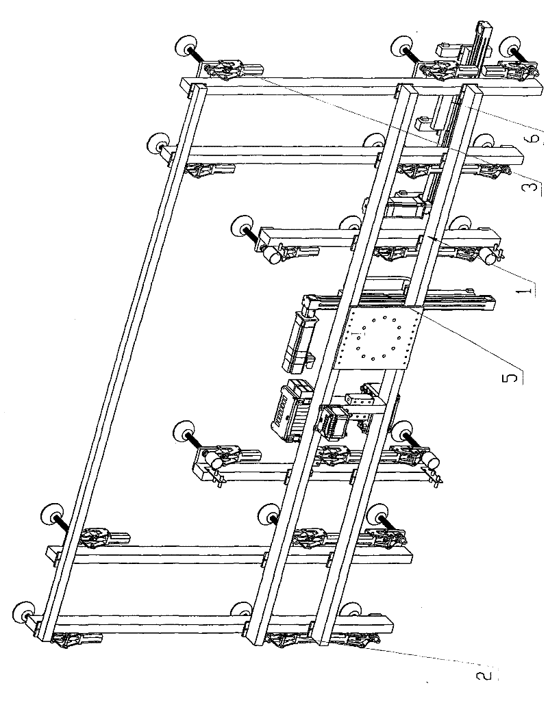
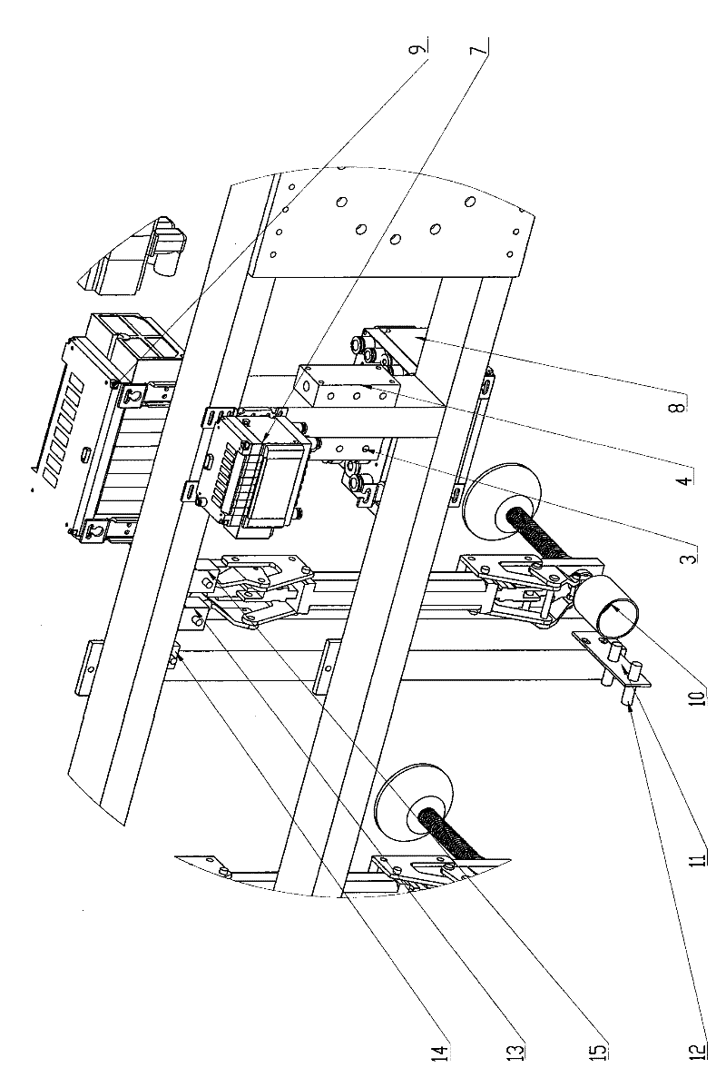
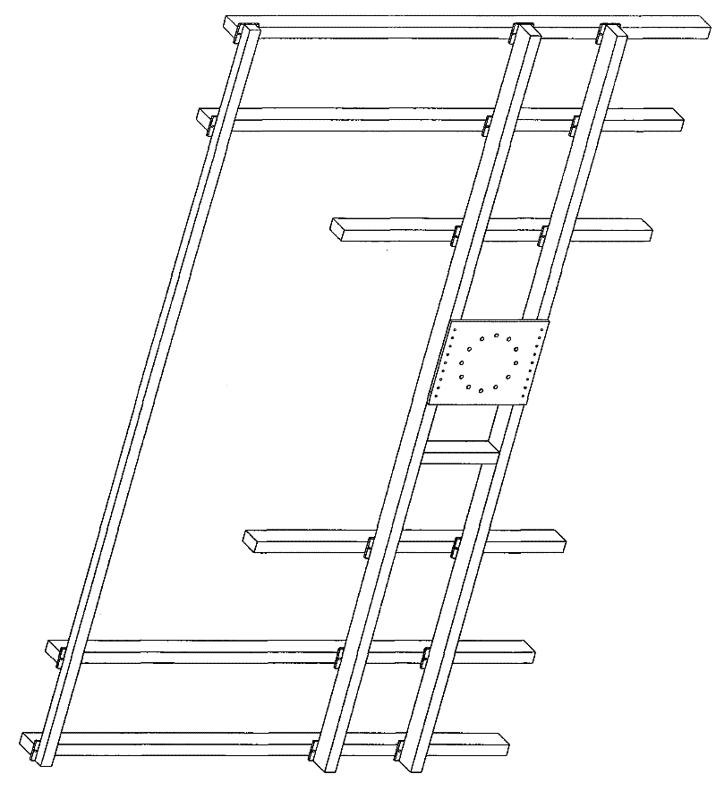
[0031] see Figure 1~2 , figure 1 It is a schematic diagram of the suction cup assembly frame used for palletizing glass at the cold end of the float glass production line according to the present invention. figure 2 for figure 1 A partial enlargement of the . Depend on figure 1 and figure 2 It can be seen that the suction cup assembly frame used for palletizing glass at the cold end of the float glass production line in the present invention includes a suction cup frame 1, eighteen sets of suction cup mechanisms 2, a first air circuit board 3, a second air circuit board 4, a A group of valve islands 7, a second group of valve islands 8, a third group of valve islands 9, a set of two-point detection components 6, a set of one-point detection components 5, four sets of anti-collision detection components 10, 11, 12 and three pressure And vacuum detection elements 13,14,15. The eighteen groups of sucker mechanisms 2 are all mounted on the bottom of the sucker frame 1 . ...


PUM


Abstract

The invention relates to a sucking disc assembling bracket for float glass production line cold side glass stacking, comprising a sucking disc bracket (1), a plurality of groups of sucking disc mechanisms (2), a set of two-point detection component (6), a set of one-point detection component (5) and four sets of anti-collision detection components (10, 11, 12); a plurality of groups of the sucking disc mechanisms (2) are arranged at the bottom part of the sucking disc bracket (1), each group of the sucking disc mechanism (2) comprises a bottom plate (2.1), a bracket(2.2), a movable plate (2.3),an air cylinder (2.4), a sucking disc (2.5), a sucking disc rod (2.6), a sucking disc rod guide sleeve (2.7), a guide sleeve fixed nut (2.8) and a spring (2.9); the two-point detection component (6) is laterally arranged at the bottom part of the sucking disc bracket (1); the one-point detection component (5) is longitudinally arranged at the bottom part of the sucking disc bracket (1), and four sets of the anti-collision detection components are arranged on the sucking disc bracket (1) in a rectangle way. The sucking disc assembling bracket for float glass production line cold side glass stacking can automatically suck the glass, after suction is carried out, the glass is detected and placed on the bracket, and the anti-collision detection is carried out in the whole process.

Description

(1) Technical field [0001] The invention relates to a stacker, in particular to a suction cup assembly frame used for stacking glass at the cold end of a float glass production line. It is mainly used for palletizing glass at the cold end of the float glass production line. (2) Background technology [0002] At present, there are more than 200 float glass production lines in my country. Glass raw materials are sold to users after melting, forming, annealing, optimized cutting, palletizing and packing. Optimized cutting refers to the original glass sheet cut on the basis of the minimum cut of defective or unqualified parts after automatic inspection and grading of the glass plate, and on the basis of meeting the national standard size; the cut glass needs to be cut according to different specifications , Palletizing and packing at different levels. The maximum production capacity of a single float line can reach 1,000 tons per day. To achieve graded palletizing and packing...

Claims


Application Information

Patent Timeline
Patent Type & Authority Patents(China)
IPC IPC(8): C03B35/00B65G47/91B65G49/06B65G61/00
CPCY02P40/57
Inventor 文碧许卫星何国昌王晨强黄小花
Owner JIANGSU JINMING IND ROBOT AUTOMATION
Learn More