
Magnetic turn-over device of sorting machine

A sorting machine and magnetic technology, used in sorting, transportation and packaging, conveyor objects, etc., can solve the problems of type limitation, inability to forge objects to receive complete inspection, inability to distinguish directions, etc.

Inactive Publication Date: 2010-06-09
SAMSUNG SCI & TECH CORP
View PDF0 Cites 19 Cited by
  • Summary
  • Abstract
  • Description
  • Claims
  • Application Information

AI Technical Summary

Problems solved by technology

[0004] Although the sorting machine used to detect forged objects in the past can achieve the purpose of detection by means of two alignments and two conveyances, this detection method is only suitable for the detection of some forged objects that can distinguish the direction, such as For forged objects such as traditional nuts and other forged objects that lack obvious directions, the direction cannot be distinguished by two full rows, so even after two full rows, the purpose of complete detection cannot be achieved.
Moreover, even if the forged object has directionality, the previous detection method needs to go through two full-line operations, which will also have the disadvantage of time-consuming detection process.
[0005] In addition, although the purpose of aligning the forged objects can be achieved by using mechanical vibration, the two alignments are carried out separately, and it is impossible to ensure that each forged object is oriented in the correct direction during the alignment process. For example, the traditional forged objects lack obvious directionality. , even after two full columns, the direction cannot be distinguished
When errors occur in the alignment or the correct direction cannot be aligned, each forged object cannot be completely inspected. Therefore, this kind of sorting machine in the past is not only limited in the types of objects suitable for inspection, but also has a high error rate during inspection. higher deletion

Method used

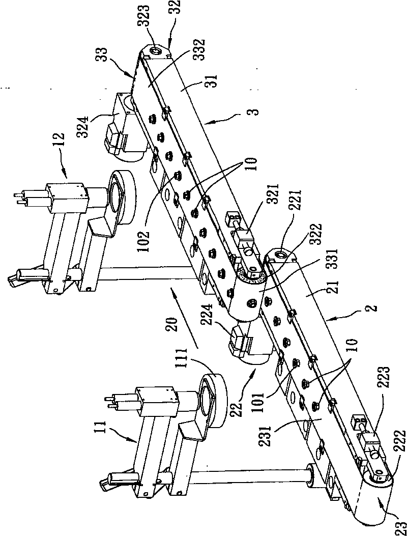

Image

  • Magnetic turn-over device of sorting machine
  • Magnetic turn-over device of sorting machine
  • Magnetic turn-over device of sorting machine

Examples


Embodiment Construction

[0016] Below in conjunction with accompanying drawing and embodiment the present invention is described in detail:

[0017] Before the present invention is described in detail, it should be noted that in the following description, similar elements are denoted by the same reference numerals.

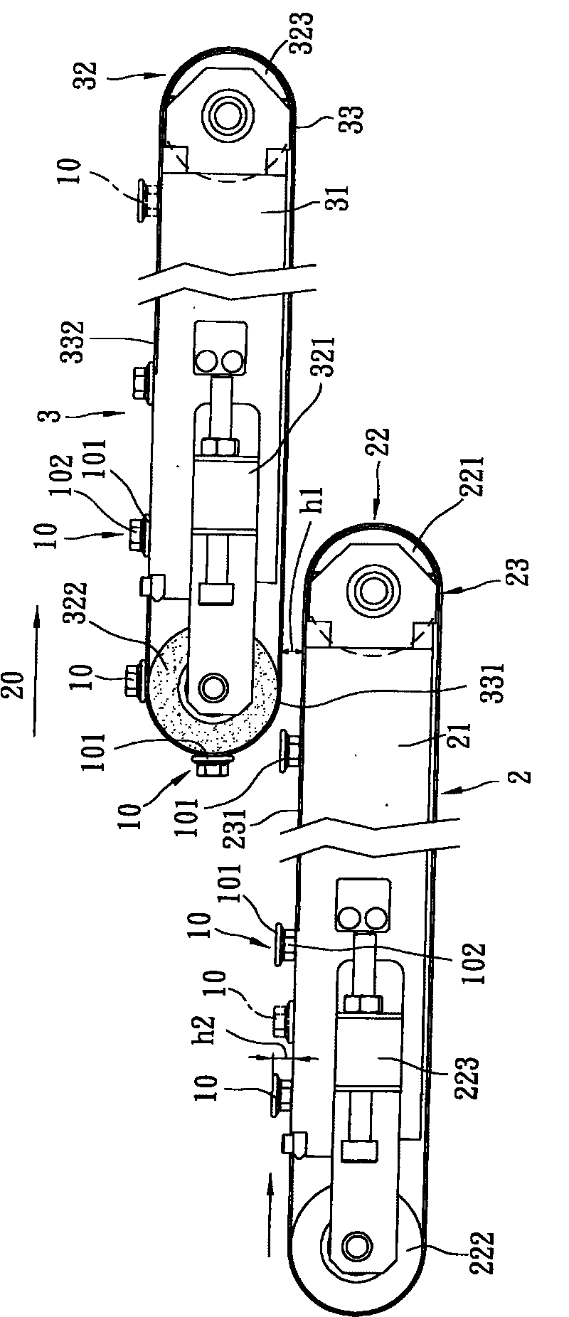
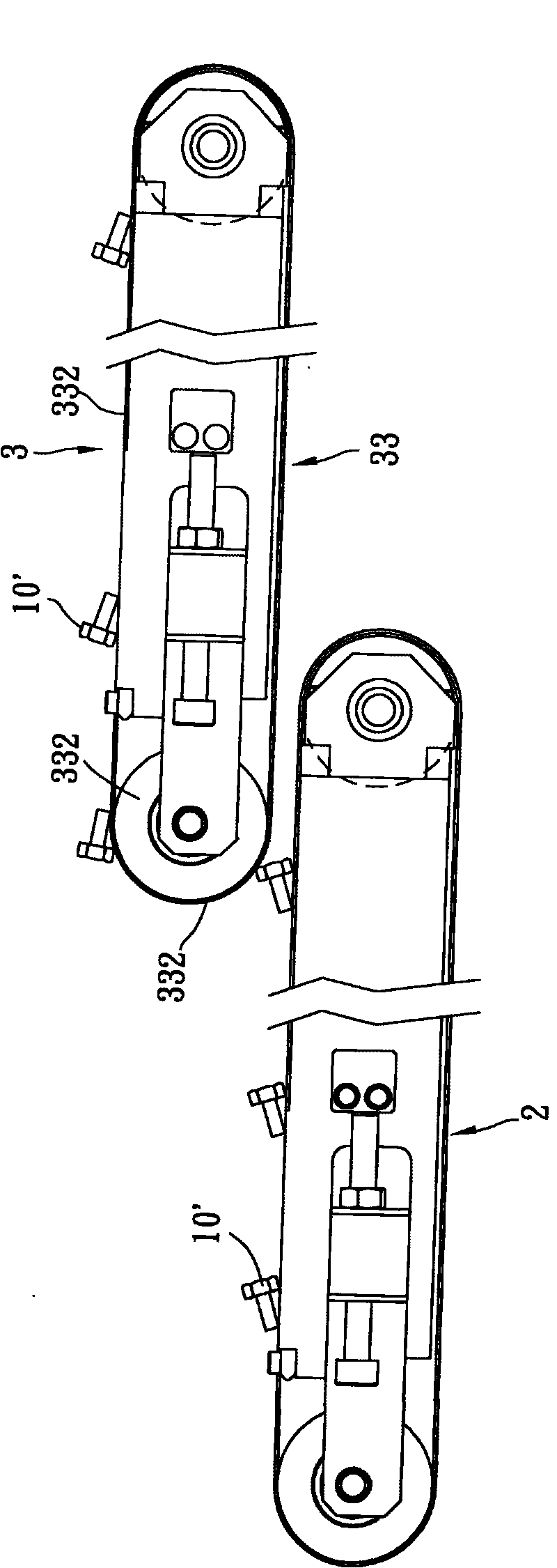
[0018] refer to figure 1 , 2 , the first preferred embodiment of the magnetic flipping device of the present invention is suitable for transporting several magnetic objects 10 with magnetism, and cooperates with two detectors 11 and 12 spaced before and after to detect the magnetic objects 10. figure 1 The detectors 11 and 12 shown in are used to detect the integrity of the surface of the magnetic object 10, but as long as the magnetic object 10 needs to be turned over in the process of detecting various physical properties of the magnetic object 10, the magnetic turning device of the present invention is suitable for use . Furthermore, the magnetic object 10 disclosed in this embodime...


PUM


Abstract

The invention discloses a magnetic turn-over device of sorting machine. The magnetic turn-over device is used for conveying a plurality of magnetic objects for detection and comprises two conveying units, each conveying unit comprises a conveyer belt and a driving wheel set for driving the conveyer belt to march along a transport direction and is provided with a conveying section for holding the magnetic objects; the rear conveying unit in the invention is also provided with a magnetic turn-over section close to the conveying section of the front conveyer belt, the magnetic turn-over section can be formed on the basis of the selection of the material for the conveyer belt body or the driving wheel set fit with the conveyer belt. By using the magnetism, the invention can perform two-side detection on the magnetic objects in one sorting and achieve the effects of saving detection time and reducing detection error probability.

Description

technical field [0001] The present invention relates to a magnetic flipping device of a sorting machine, in particular to a magnetic flipping device of a sorting machine which utilizes the principle of magnetism to change the arrangement direction of the conveyed magnetic objects so as to facilitate the detection of both sides of the magnetic objects . Background technique [0002] In the past, when forging objects such as screws and nuts were manufactured, the metal wire was first cut into an appropriate length, and then the wire was forged into a predetermined shape by several forging processes. During the forging process, forging Items are subjected to multiple impacts, therefore, there may be imperfections such as breakage, unevenness, etc. on the finished product. In order to ensure the quality of shipments, in the past, various inspections were carried out on forged objects before leaving the factory. The inspection machines used to judge the surface integrity of forg...

Claims


Application Information

Patent Timeline
Patent Type & Authority Applications(China)
IPC IPC(8): B07C5/02B65G47/14B65G47/248B07C5/34
Inventor 杨耀隆
Owner SAMSUNG SCI & TECH CORP
Learn More