Tooth shape processing and molding method of hollow pipe fitting and special mold thereof

A technology for processing and forming hollow tubes, which is applied to forming tools, other household appliances, household appliances, etc., can solve the problems of high cost, affecting the rigidity of parts, perforation of pipe fittings, etc., and achieves the effect of simple method and guaranteed rigidity.

Inactive Publication Date: 2012-07-18
侯帅
View PDF0 Cites 0 Cited by
  • Summary
  • Abstract
  • Description
  • Claims
  • Application Information

AI Technical Summary

Problems solved by technology

Since the depth of special-shaped teeth is generally close to the wall thickness of the pipe fittings or even exceeds the wall thickness of the pipe fittings, the use of cutting methods for tooth shape forming may easily lead to perforation of the pipe fittings and affect the rigidity of the parts; using ordinary punching and extrusion molding methods, since the parts are hollow parts, The rigidity of the top surface is poor, and the material of the top surface of the hollow pipe is in a cantilever state during the extrusion process, and the bending strength of the material surface is less than the material yield strength and elongation, so the surface of the workpiece working area has not yet been formed. Defects such as collapse and compression occur. For example, adding fillers to hollow pipes and then performing extrusion processing, it is difficult to remove the fillers after the tooth profile is formed, and the processing process is many and the cost is high.

Method used


Image

  • Tooth shape processing and molding method of hollow pipe fitting and special mold thereof
  • Tooth shape processing and molding method of hollow pipe fitting and special mold thereof
  • Tooth shape processing and molding method of hollow pipe fitting and special mold thereof

Examples


Embodiment Construction

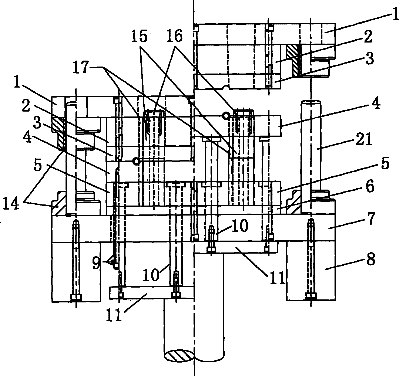
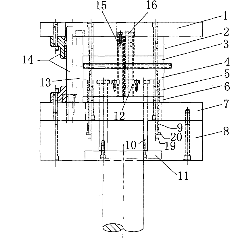
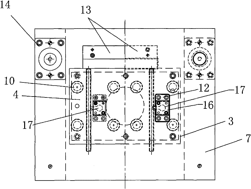
[0012] See figure 1 , the tooth shape processing and forming method of the hollow pipe fitting of the present invention, the pipe fitting to be processed is clamped by the upper clamping plate 3 and the lower clamping plate 4, and the forming punch 17 is downward along the tangential direction of the pipe wall of the tooth profile processing part of the pipe fitting to be processed sports. The forming surface of the forming punch is a slope; the slope of the slope is not more than 1.5 degrees; the material of the pipe fitting to be processed is a high-frequency welded pipe; when the tooth width of the pipe fitting to be processed is greater than 5mm, the tooth depth is greater than 1.8mm or the wall thickness of the pipe fitting is greater than 1.8mm First, cut off 20% to 30% of the wall thickness of the pipe material, and then use the forming punch 4 to punch down along the tangential direction of the pipe wall.

[0013] The special mold for the tooth shape processing and fo...


PUM


Abstract

The invention provides a tooth shape processing and molding method of a hollow pipe fitting, which can ensure that the tooth-shaped surface of the hollow pipe fitting has no defects of collapse, pressure collapse and the like, keep a certain wall thickness of the tooth-shaped part of the pipe fitting, achieve the design process requirements of a product, and the invention further provides a special mold. The special mold comprises an upper mold structure and a lower mold structure, wherein the upper mold structure is connected with a sliding block of a machine tool, the lower mold structure is connected with a lower push-up cylinder of the machine tool, the upper mold structure and the lower mold structure are guided and positioned through an independent sliding guide column structure, the upper mold structure comprises an upper template, a lower padding plate and an upper material pressure plate, the lower mold structure comprises a lower template, the lower template is mounted on a lower padding block, and the lower padding plate and a lower fixing plate are mounted at the upper part of the lower template. The special mold is characterized in that the special mold further comprises a molding punch assembly, a molding guide rod is mounted on the molding punch assembly, a molding punch is mounted on the molding guide rod, and the molding punch assembly is vertically mounted onthe lower mold structure. The upper material pressure plate and a lower material pressure plate clamp the pipe fitting to be processed, and the method is characterized in that the molding punch movesdownwards along the vertical tangent direction of the outer wall of the pipe fitting to be processed.

Description

(1) Technical field [0001] The invention relates to the technical field of surface tooth profile processing of annular hollow pipe fittings, in particular to a tooth profile processing and forming method for hollow pipe fittings and a special mold thereof. (2) Background technology [0002] In order to save energy, reduce emissions, reduce vehicle weight and reduce energy consumption, car manufacturers have changed the structural parts of some models into hollow pipe structures. For example, the headrest frame support rod above the car seat has a hollow tubular structure as a whole, and the surface has several depths. For tooth types with different shapes and sizes, the process requires that the surface of the tooth type must not have a collapse angle, and the tooth type must maintain a certain wall thickness. Since the depth of special-shaped teeth is generally close to the wall thickness of the pipe fittings or even exceeds the wall thickness of the pipe fittings, the use ...

Claims


Application Information

Patent Timeline
Patent Type & Authority Patents(China)
IPC IPC(8): B21D22/02B21D53/28B21D37/10B21D37/12
Inventor 穆宜权黄健
Owner 侯帅
Why Eureka
Try Eureka