
Device and method for supporting processor silicon post debugging

A technology for processors and debugging hosts, which is applied in the detection of faulty computer hardware, functional testing, etc., to achieve the effect of reducing the complexity of debugging

Active Publication Date: 2012-05-23
LOONGSON TECH CORP
View PDF3 Cites 0 Cited by
  • Summary
  • Abstract
  • Description
  • Claims
  • Application Information

AI Technical Summary

Problems solved by technology

There are some methods in the prior art to use special recording chips, or logic analyzers to capture external input, but it is difficult and costly to implement, so a better debugging device and method are needed to solve this problem

Method used


Image

  • Device and method for supporting processor silicon post debugging
  • Device and method for supporting processor silicon post debugging
  • Device and method for supporting processor silicon post debugging

Examples


Embodiment Construction

[0030] In order to make the purpose, technical solution and advantages of the present invention clearer, the device and method for supporting post-silicon debugging of processors of the present invention will be further described in detail below in conjunction with the accompanying drawings and embodiments. It should be understood that the specific embodiments described here are only used to explain the present invention rather than limit the present invention.

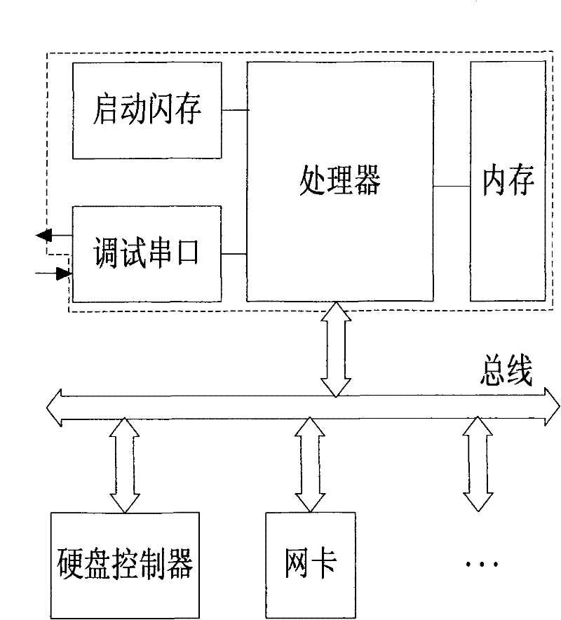
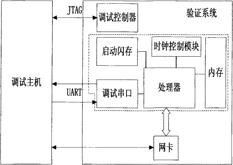
[0031] The present invention is based on figure 1 Based on the common processor system shown, the definition implements a basic system such as figure 1 As shown in the dotted line box, it is only composed of the necessary components to verify the processor, including processor core, memory, boot flash memory, serial port output and clock control module. When the verification software is limited to run within the basic system, there is no external input signal. Therefore, on the premise that the basic system is dete...


PUM


Abstract

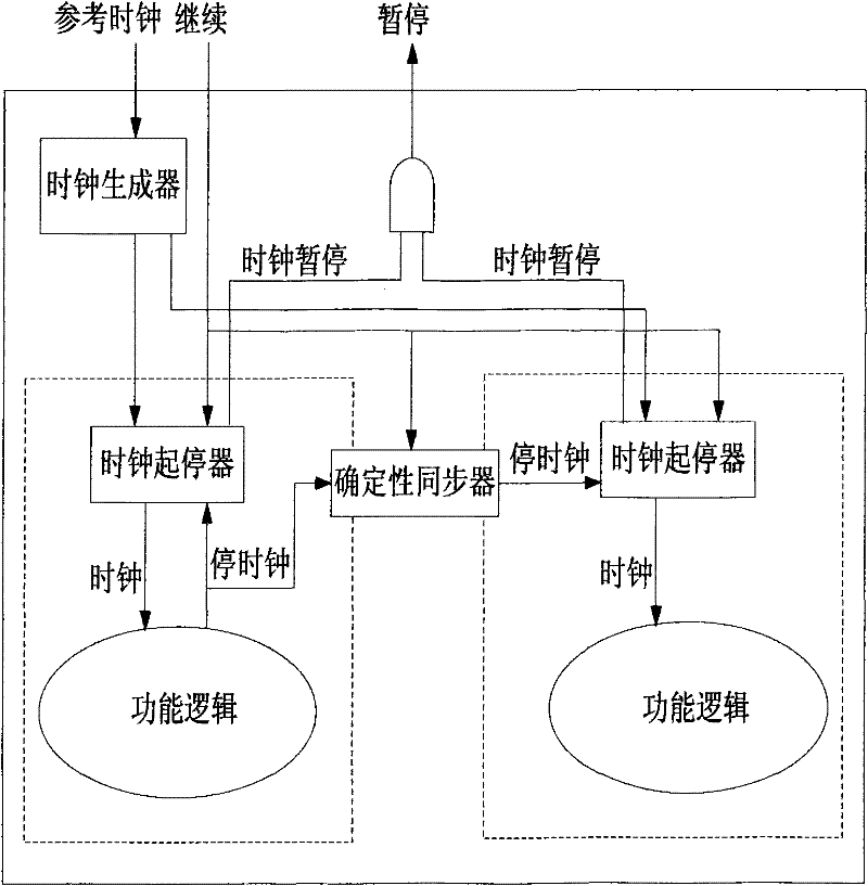
The invention discloses a device and a method for supporting processor silicon post debugging. The device comprises a debugging host and a verification system which comprises a basic system, a debugging controller and a network card. The basic system comprises a processor core, a memory, a boot flash, a serial output and a clock control module. The clock control module is used for stopping each functional clock with certainty, thereby entering a halted state, and under the halted state, all internal states in the processor can be accessed by a scanning chain for a test interface. The verification system also comprises a debugging controller used for being connected with the debugging host, so as to lead the debugging host to remotely read or control the interface signal of the basic system.

Description

technical field [0001] The invention relates to the field of computer system verification, more specifically to the field of post-silicon debugging of processors, in particular to a device and method for supporting post-silicon debugging of processors. Background technique [0002] In the field of computer system verification, as the scale of the chip increases, there will inevitably be errors in the first tape-out, so post-silicon debugging is required, but because most of the signal changes occur inside the silicon chip, the design It is difficult for personnel to understand the working conditions of the chip, so it will cause great difficulties in debugging. [0003] The general debugging support method adds some analysis logic in the chip, and collects the internal working conditions into the memory, so that the internal signals can be seen. The main disadvantage of this method is that the number of signals collected and the length of time are limited by the memory cap...

Claims


Application Information

Patent Timeline
Patent Type & Authority Patents(China)
IPC IPC(8): G06F11/26
Inventor 苏孟豪陈云霁
Owner LOONGSON TECH CORP
Learn More