Pressure gauge

A technology of pressure and pressure sense, which is applied in the field of pressure gauges to achieve the effects of high-efficiency manufacturing, low heating noise, and compact size

Inactive Publication Date: 2010-05-19
NXP BV
View PDF8 Cites 11 Cited by
  • Summary
  • Abstract
  • Description
  • Claims
  • Application Information

AI Technical Summary

Problems solved by technology

Traditionally, in the field of MEMS piezoresistive resonators, this temperature dependence of the resonant frequency has been considered a drawback

Method used


Image

  • Pressure gauge
  • Pressure gauge
  • Pressure gauge

Examples


Embodiment Construction

[0047] Certain aspects of the principles employed in the Pirani gauge will first be described, which will assist in understanding the embodiments of the invention which will be described below.

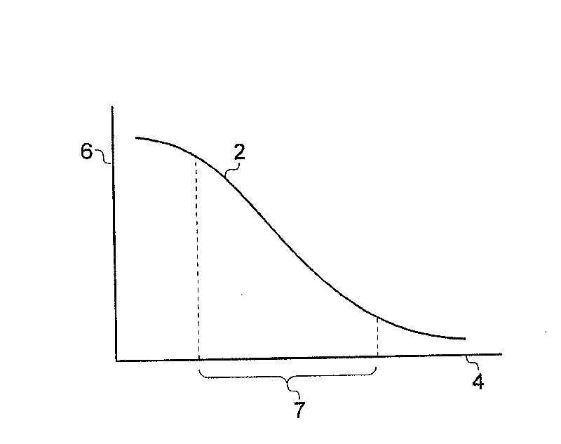
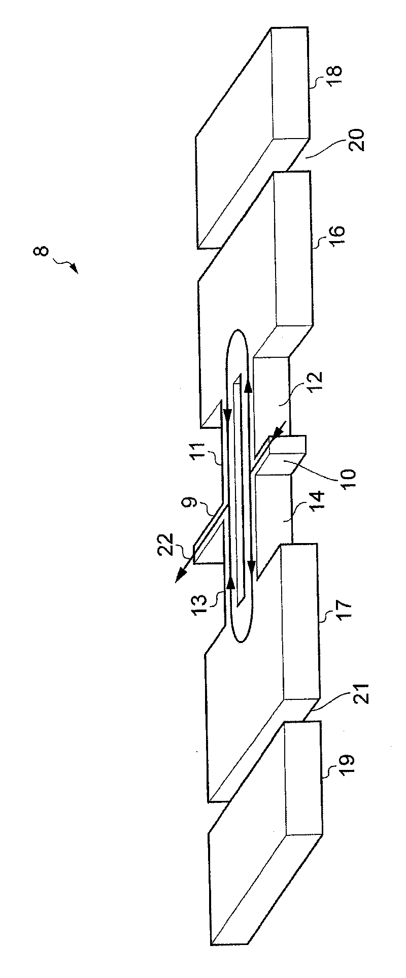
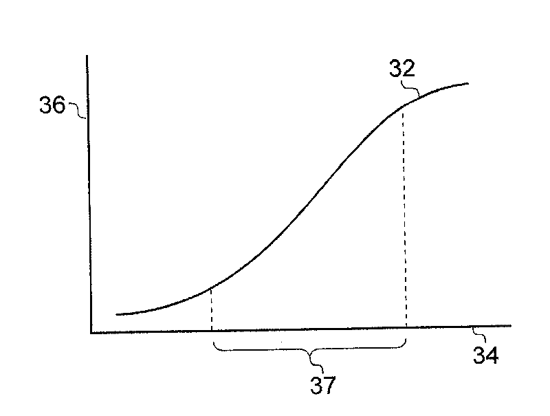
[0048] The general structure of a Pirani gauge consists of a heating element well thermally insulated from the environment (some air space must exist between the element and its environment), and means for sensing the temperature of the heating element. The thermal conductivity k from the heating element to the heat sink (ambient) depends on the air pressure p and can be written as:

[0049] k ( p ) = k solid + k gas ( ∞ ) ( p / p 0 1 + p ...


PUM


Abstract

A pressure / vacuum sensor and method, comprising: driving a MEMS piezoresistive resonator (8) into resonant vibration, applying Joule heating to the resonator (8); and sensing a variable parameter that varies in response to the tendency of the resonant frequency (fo) to depend upon the temperature of the resonator (8), the temperature thereof depending upon the pressure. The variable parameter may be the resonant frequency of the resonator (8), or a change therein, or may be derived from a feedback loop, being for example a time integrated feedback signal (82) or a reading (94) of the sense current (22), the loop keeping the resonant frequency constant in opposition to the above mentioned tendency. A reference MEMS capacitive resonator (62) may be located in the vicinity of the resonator (8) for compensating purposes.

Description

technical field [0001] The present invention relates to pressure gauges (also known as pressure sensors). The invention is particularly suitable for, but not limited to, pressure gauges (or sensors) for use as vacuum gauges (or sensors). Background technique [0002] Pressure gauges (also called pressure sensors, hereinafter the terms "gauge" and sensor both mean gauge or sensor) are known, in particular vacuum gauges. [0003] A well known example of a vacuum gauge is the Pirani gauge. A Pirani gauge consists of a heating element placed in the environment / gas to be measured, and means for sensing the temperature of the heating element. With the environment acting as a heat sink, the heat conduction from the heating element to the environment depends on the air pressure. The heating element is continuously supplied with constant Joule heating, which is eventually balanced with heat loss. The resulting element temperature is used to indicate pressure, where the element te...

Claims


Application Information

Patent Timeline
Patent Type & Authority Applications(China)
IPC IPC(8): G01L9/00G01L21/00G01D5/00H03H3/00
CPCG01L21/22G01L9/0022H03H2009/02496H03H9/2452H03H9/02259
Inventor 金·范乐约瑟夫·T·M·范贝克
Owner NXP BV
Why Eureka
Try Eureka