Brushless direct-current motor and circuit board quick connecting device

A technology of brush DC motor and quick connection, which is applied in the direction of electromechanical devices and electrical components, can solve the problems of low production efficiency, high production cost, complicated disassembly and assembly process, etc., and achieve the effect of improving production and saving manufacturing cost

Inactive Publication Date: 2010-05-19
WOLONG ELECTRIC GRP CO LTD
View PDF0 Cites 3 Cited by
  • Summary
  • Abstract
  • Description
  • Claims
  • Application Information

AI Technical Summary

Problems solved by technology

Although this connection method can ensure a reliable connection between the printed circuit board and the motor winding and the electrical signal at the connection can pass through well, it must be placed on the other side of the SMD Hall element. To weld the windings of the motor, so the printed circuit board must be designed as a double-sided board, which increases the manufacturing cost of the printed circuit board
Manual welding is required during the assembly of printed circuit boards, which increases manpower and process costs and reduces production efficiency
When disassembling the printed circuit board for motor maintenance, it is necessary to manually suck out the solder from the solder joints to disassemble the printed circuit board, which is not suitable for batch operations during motor maintenance
[0004] Therefore, the existing brushless DC motor circuit board connection method has disadvantages such as high production cost and complicated disassembly process during motor production and manufacturing.

Method used


Image

  • Brushless direct-current motor and circuit board quick connecting device
  • Brushless direct-current motor and circuit board quick connecting device
  • Brushless direct-current motor and circuit board quick connecting device

Examples


Embodiment Construction

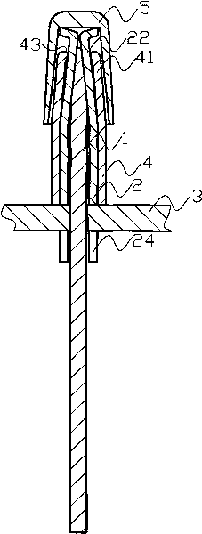
[0019] The technical solution of the present invention will be further described in detail below in conjunction with the accompanying drawings.

[0020] like figure 1 , 2 As shown, the present invention includes a strip-shaped conductive pin 1 electrically connected to the motor winding, and a connector 2 fixed on the circuit board 3 that cooperates with the conductive pin 1. The connector 2 includes a connecting seat 21 and is located on the connecting seat 21. The four "7"-shaped metal shrapnel 22 that can hold the conductive pin 1, the four shrapnel 22 are symmetrically arranged on the connecting seat 21, and the inner walls thereof are combined to form a socket cavity 23 with a lower size and an upper size to cooperate with the conductive pin 1, In order to increase the contact surface, the head of the conductive pin 1 has a bevel; in order to increase the strength of the elastic piece 22 and prevent excessive deformation, a limiter 4 is provided outside the connector 2, ...


PUM


Abstract

The invention provides a brushless direct-current motor and circuit board quick connecting device, relating to a motor device; the existing brushless direct-current motor and circuit board quick connecting device has high production cost and complex dismounting process; the quick connecting device comprises an electric-conduction contact pin (1) electrically connected with a motor winding, and a connector (2) which is matched with the electric-conduction contact pin (1) for being fixed on the connector (2) of a circuit board (3), the connector (2) comprises a connecting base (21) and a plurality of metal spring plates (22) which can clamp the electric-conduction contact pin (1) and is arranged on the connecting base (21), and the spring plates (22) are electrically connected with the circuit board (3); the circuit board (3) is inserted in an insertion cavity formed by the spring plates, so as to realize dismountable connection, achieve the purpose of the electrical connection of the winding and the circuit board and discard the connecting mode of manual welding; in addition, single-surface routing is carried out to distribute the board, so as to save the manufacturing cost of a printed circuit board; in addition, the production, assembly and maintaining efficiency can be improved.

Description

【Technical field】 [0001] The invention relates to a motor device, in particular to a connection device between a motor and a circuit board. 【Background technique】 [0002] In the control scheme built into the printed circuit board of the brushless DC motor, the Hall element of the printed circuit board of the brushless DC motor must generally be installed on the side of the permanent magnet rotor of the motor to reliably measure the rotor position. In the manufacturing process of the brushless DC motor, the printed circuit board with the Hall element should be installed on the motor body, and the printed circuit board should be removed from the motor body during maintenance. In the manufacturing process, the connection between the printed circuit board and the various windings of the motor must be considered. When the printed circuit board is connected, it is necessary to ensure that the connection is well-conducted, so that a reliable connection between the motor winding a...

Claims


Application Information

Patent Timeline
Patent Type & Authority Applications(China)
IPC IPC(8): H02K29/08
Inventor 郝兆礼杜荣法方巧珍廉晨龙翟德虎
Owner WOLONG ELECTRIC GRP CO LTD
Why Eureka
Try Eureka