Eureka AIR delivers breakthrough ideas for toughest innovation challenges, trusted by R&D personnel around the world.

Wind-power-station power output counterbalance system and working method thereof

A technology of power output and balance system, applied in flexible AC transmission system, wind power generation, AC network load balancing, etc. Market application prospects and actual production value, the effect of eliminating vacuum suppression belts and reducing energy consumption

Active Publication Date: 2010-05-19
STATE GRID CORP OF CHINA +1
View PDF1 Cites 13 Cited by
  • Summary
  • Abstract
  • Description
  • Claims
  • Application Information

AI Technical Summary

Problems solved by technology

[0007] Although the above several existing technologies can reduce power fluctuations, each still has its own disadvantages: Although scheme 1 can reduce power fluctuations, it requires the conventional power grid to also be DC transmission, and the investment of converter equipment at both ends is large, and the exchange power is not high. When it is large, the economy is poor, and this method is often not feasible
Option 3 is based on the usual compensation principle to smooth the output of the wind farm, but the energy consumption of the energy storage device and the loss between energy are the main factors restricting the practical application. In addition, due to the asynchrony between the detection time and the compensation time, there is a vacuum compensation zone, that is, the lag time for taking compensation actions, that is, the time difference between the compensation time and the detection time, which has an adverse effect on the system

Method used


Image

  • Wind-power-station power output counterbalance system and working method thereof
  • Wind-power-station power output counterbalance system and working method thereof
  • Wind-power-station power output counterbalance system and working method thereof

Examples


Embodiment

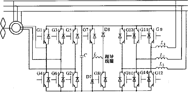
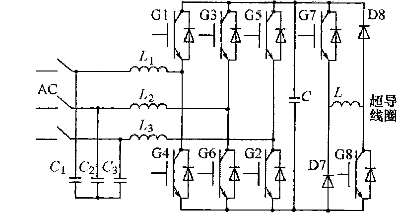
[0041] Embodiment: a kind of wind farm power output balance system (see figure 2 ), which is characterized in that it is composed of a wind speed acquisition conversion circuit, an actual wind farm simulation module, a differential amplifier circuit, a comparison circuit, a control circuit, a converter and a superconducting magnetic storage including a chopper, a filter and a feedback circuit. The output terminal of said wind speed collection conversion circuit is connected to the actual wind farm simulation module, the output terminal of said actual wind farm simulation module is connected to a differential amplifier circuit, and the output terminal of said differential amplifier circuit is connected to a comparative circuit, the output terminal connected to the comparison circuit is connected to the control circuit, the output terminal of the control circuit is connected to the converter, the output terminal of the converter is connected to the superconducting magnetic energ...


PUM


Abstract

The invention relates to a wind-power-station power output counterbalance system which comprises a wind speed acquisition and conversion circuit, an actual wind-power-station analog module, a differential amplifying circuit, a comparison circuit, a control circuit, a current transformer and a superconducting magnetic energy storage device, wherein the superconducting magnetic energy storage device comprises a chopper, a wave filter and a feedback circuit. The working method of the wind-power-station power output counterbalance system comprises the following steps: (1) converting a wind signal into an electric signal; (2) producing a signal which has the same output variation law as the actual wind power station; (3) processing by the differential amplifying circuit; (4) performing the circuit comparison with the power signal output by the superconducting energy storage device; (5) and controlling the conduction of a triode in the current transformer, and outputting power of the multiple superconducting energy storage devices. The invention has the advantage of storing the electric energy by utilizing the superconducting magnet, thereby greatly enhancing the energy storage density, reducing the energy consumption and realizing the synchronous inhibition on the power output fluctuation of the wind power station.

Description

(1) Technical field: [0001] The invention relates to a power output balance system of a wind farm, which belongs to the technical field of electric engineering. (two) background technology: [0002] With the requirements of economic development (that is, the capacity of modern power systems is increasing) and the depletion of conventional energy sources, distributed power generation (such as wind power generation, photovoltaic power generation, tidal power generation, etc.) has attracted more and more attention. In recent years, wind power technology has developed rapidly, and it is the most mature technology, most suitable for large-scale development conditions and commercialization prospects among non-hydro renewable energy power generation, and is favored by the energy circles all over the world. When it is connected to the conventional grid, especially the grid connection of large-capacity and high-proportion wind farms, due to the volatility and intermittent characteris...

Claims


Application Information

Patent Timeline
Patent Type & Authority Applications(China)
IPC IPC(8): H02J3/28H02J3/38H02J3/01
CPCY02E10/763Y02E70/30Y02E40/10Y02E40/67Y02E10/766Y02E10/76Y02E40/40Y02E40/60
Inventor 周雪松权博马幼捷李圣明程德树宋代春田密
Owner STATE GRID CORP OF CHINA
Why Eureka
Eureka Blog
Learn More