Rubber injection machine balance injection structure

An injection machine and balancing technology, which is applied to the field of balanced injection structure of rubber injection machines, can solve the problems of inconvenient control of rubber material temperature, easy vulcanization of rubber material at the nozzle mouth, large pressure loss of rubber material, etc. The effect of reducing the vulcanization amount of the rubber compound and having a simple and reasonable structure

Active Publication Date: 2012-02-01
广东伊之密精密橡塑装备科技有限公司
View PDF1 Cites 0 Cited by
  • Summary
  • Abstract
  • Description
  • Claims
  • Application Information

AI Technical Summary

Problems solved by technology

[0003] The disadvantage of the first structure is: the height of the whole machine is too high, which is not conducive to the installation of low workshops;
[0004] The disadvantage of the second structure is: because the weight deviation between the injection cylinder and the plasticizing part is too large, the lifting action of the injection platform cannot be performed, and the rubber at the nozzle port is easy to vulcanize;
[0005] The disadvantage of the third structure is: because the plasticizing and injection parts are on one side, and the plasticizing part is installed inside the injection part, it is not convenient to control the temperature of the rubber material, and the accuracy of the injection volume is not as high as the first two.
[0006] The disadvantage of the fourth structure is: because the injection barrel is placed horizontally, its flow path is 90 degrees to the nozzle body, the pressure loss of the rubber material is large during injection, and it is only suitable for the rubber material with low Mooney viscosity.
The structure is complex and the height of the whole machine is high, which is not conducive to the installation of low-level workshops

Method used


Image

  • Rubber injection machine balance injection structure
  • Rubber injection machine balance injection structure
  • Rubber injection machine balance injection structure

Examples


Embodiment Construction

[0024] The present invention will be further described below in conjunction with the accompanying drawings and embodiments.

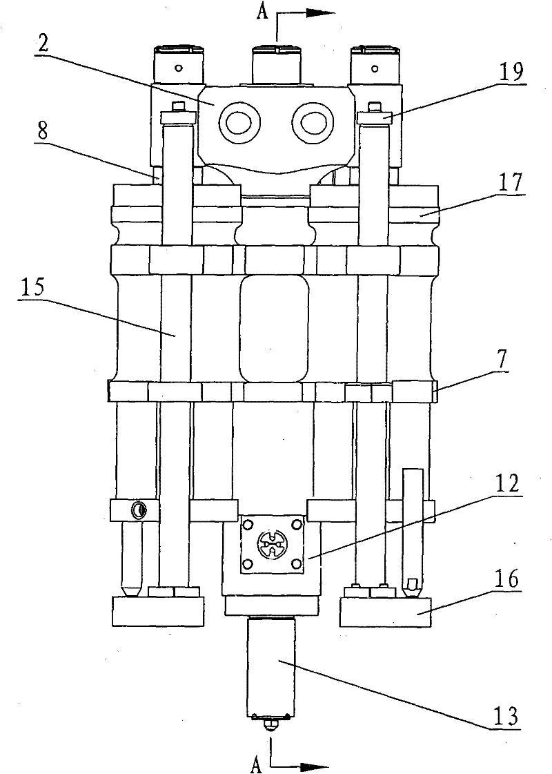
[0025] see Figure 1-Figure 6 The rubber injection machine has a balanced injection structure, including an upright injection barrel 12, the side is connected to the plasticizing part (not shown in the figure) at 90 degrees, and an injection plunger head 11 connected to the injection cylinder 17 is provided inside. , the lower end is directly equipped with a nozzle body 13, and the lower end of the nozzle body is provided with a nozzle 14.

[0026] There are three injection cylinders 17, which are evenly distributed in a triangle on the side of the injection cylinder 12, parallel to the injection cylinder, and fixedly connected to the injection cylinder through the oil cylinder support 7; the center of the injection cylinder is located at the center of gravity of the triangle. Its injection plunger head 11 is in drive connection with the piston rod 6 o...


PUM


Abstract

A balanced injection structure for a rubber injection machine, comprising an upright injection barrel connected to a plasticizing part, with an injection plunger head in transmission connection with an injection cylinder, a nozzle body at the lower end, and an injection cylinder with a There are more than two, which are evenly distributed on the side of the injection barrel, and the piston rod of the injection cylinder is connected with the transmission plunger head of the injection cylinder. The injection part of the present invention is placed vertically, but the injection cylinder and the injection barrel are arranged in a plane and parallel, so that the height of the whole machine is reduced; the plasticizing part and the injection part are independent, the temperature control of the plasticizing and injection parts is easy to control, and the nozzle opening is reduced The amount of vulcanization of the rubber material, and the cleaning of the rubber material is convenient; at the same time, there are more than two injection cylinders, which are evenly distributed on the side of the injection barrel, and the piston rod is connected to the injection plunger head of the injection barrel through a beam. When injecting, the piston rod retracts and pulls the crossbeam; the crossbeam pushes the injection plunger head, and the injection plunger head pushes the rubber to be injected through the inner flow channel of the nozzle body.

Description

technical field [0001] The invention relates to a rubber injection molding machine, in particular to a balanced injection structure of the rubber injection machine. Background technique [0002] The injection devices of several traditional rubber injection machines are: 1. The plasticizing barrel and the injection cylinder are at 90 degrees, single-cylinder injection, and the injection cylinder and the injection barrel are 180 degrees on a straight line; 2. The plasticizing barrel and the injection cylinder The oil cylinder forms a 180-degree single injection cylinder; 3. The plasticizing cylinder and the injection cylinder are on one side, and the plasticizing part is installed in the injection cylinder, and the method of double injection cylinders; 4. The double-cylinder horizontal injection structure, the plasticizing part It is arranged 180 degrees with the injection barrel, and two injection cylinders are installed horizontally on both sides. [0003] The disadvantage ...

Claims


Application Information

Patent Timeline
Patent Type & Authority Patents(China)
IPC IPC(8): B29C45/53
Inventor 王诗海王伟霞许飞刘成兵李小海
Owner 广东伊之密精密橡塑装备科技有限公司
Why Eureka
Try Eureka