Device for blow-molding containers

A blow molding and container technology, applied in the direction of valve operation/release device, valve device, valve housing structure, etc., can solve the problems of increased compressed gas consumption, increased operating costs, etc., to achieve easy assembly and small flow resistance , the effect of precise control

Active Publication Date: 2010-05-12
KHS GMBH +1
View PDF10 Cites 4 Cited by
  • Summary
  • Abstract
  • Description
  • Claims
  • Application Information

AI Technical Summary

Problems solved by technology

[0009] The volume of the flow path will thus lead to a delay in the desired build-up of pressure in the preform or container, since the amount of compressed gas required to fill the flow path must also be used in addition to the actually required amount of compressed gas. The compressed gas volume flows through the valve. This, in addition to a corresponding process delay, also leads to an increased compressed gas consumption and thus a corresponding increase in operating costs.

Method used


Image

  • Device for blow-molding containers
  • Device for blow-molding containers
  • Device for blow-molding containers

Examples


Embodiment Construction

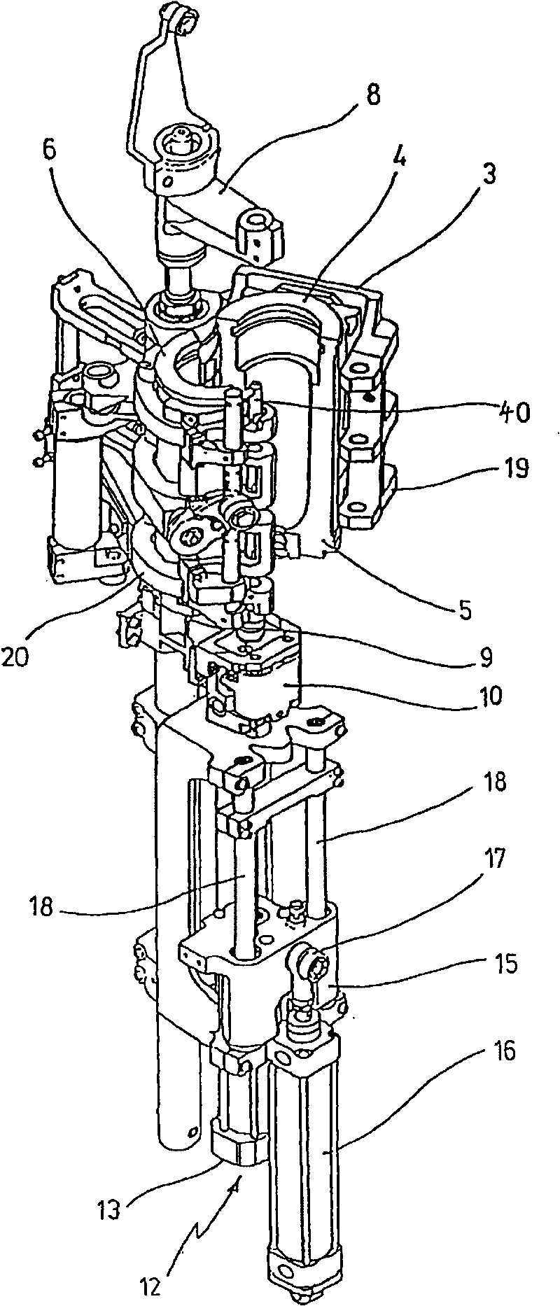
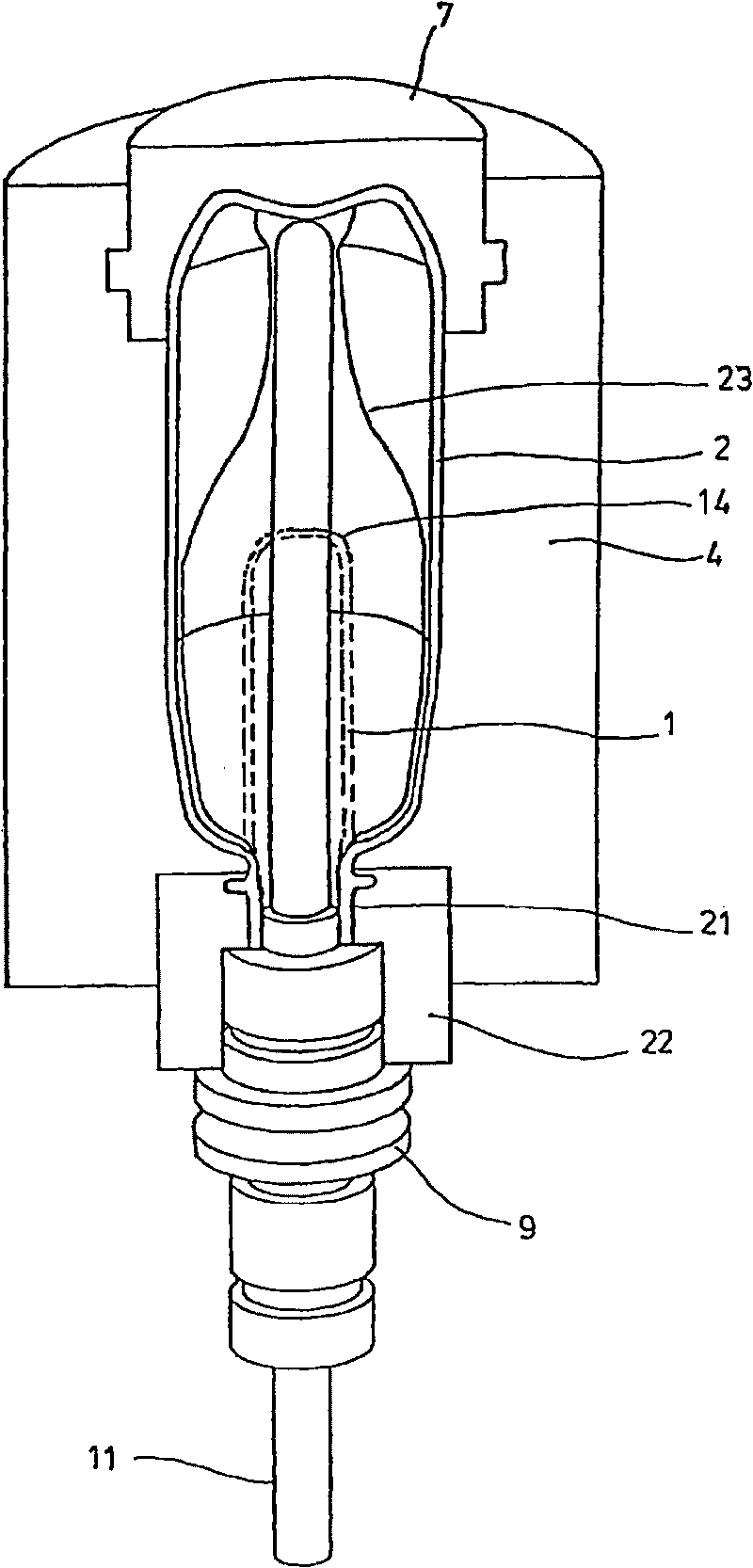
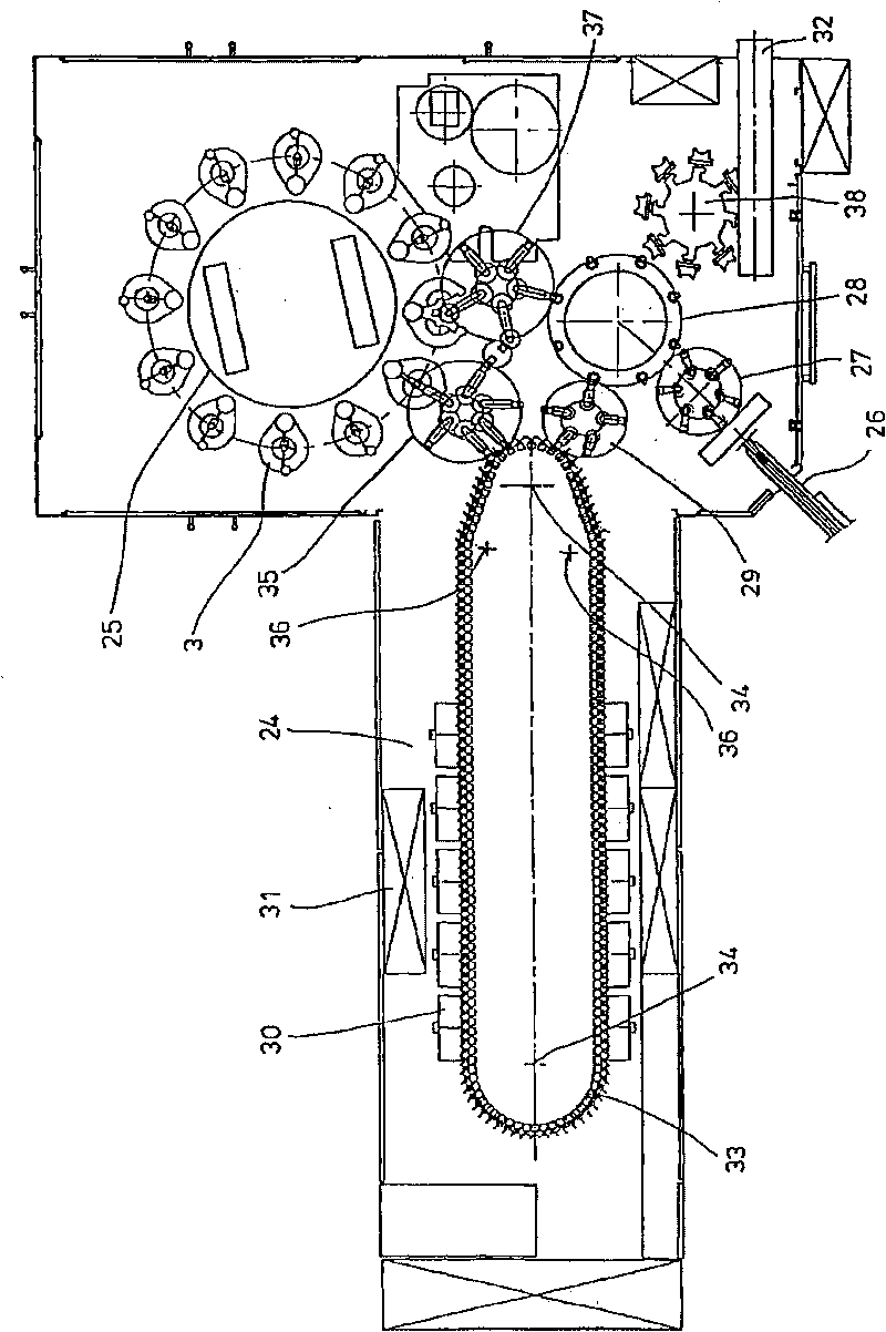
[0036] exist figure 1 with 2 The schematic structure of a device for forming preforms 1 into containers 2 is shown in .

[0037] The device for shaping the container 2 basically comprises a blow molding station 3 provided with a blow mold 4 into which the preform 1 can be inserted. The preform 1 can be an injection molded part made of polyethylene terephthalate. In order to allow the introduction of the preform 1 into the blow mold 4 and to allow the removal of the finished container 2, the blow mold 4 consists of mold halves 5, 6 and a bottom part 7 which can be lifted by a lifting device. 8 positioning. The preforms 1 can be held in the region of the blow molding station 3 by a transport mandrel 9 which, together with the preforms 1 , passes through several processing stations within the device. However, it is also possible to insert the preform 1 directly into the blow mold 4 , for example by means of pliers or another operating mechanism.

[0038] In order to allow th...


PUM


Abstract

The invention relates to a device for blow-molding containers, comprising at least one blow-molding station having a blow mold. A flow path for a blow gas for blow-molding the containers extends through a connecting element. Said connecting element has a valve support supporting at least one valve. Said valve encircles a main channel of the valve support.

Description

technical field [0001] The invention relates to a device for blow molding containers, which device has at least one blow molding station with a blow mold, and in which device the flow path for the blowing gas passes through a connection The element extends, the blowing gas is used to blow mold the container, the connecting element has a valve carrier, which holds at least one valve. Background technique [0002] When forming containers by means of blow molding pressure, preforms made of thermoplastic material, for example PET (polyethylene terephthalate), are fed to different workstation. Typically, such a blow molding machine has a heating device and a blow molding device, in the region of which the previously temperature-treated preform is expanded by biaxial orientation to form the container. The expansion takes place by means of compressed air which is introduced into the preform to be expanded. DE-OS 43 40 291 explains the process for such an expansion of the preform...

Claims


Application Information

Patent Timeline
Patent Type & Authority Applications(China)
IPC IPC(8): B29C49/42F16K27/00F16K31/122
CPCB29C2049/1257B29C49/42B29C49/58B29K2023/12B29C49/4289B29C49/12B29C2049/5803B29C33/26B29K2067/00B29C2049/1271B29C49/1222B29C49/1229B29C49/42075B29C49/42085B29C49/42087B29C2049/7831B29C2049/7832
Inventor K·鲍尔M·林克M·利岑贝格M·凯勒D·阿布德哈尔登P·博斯
Owner KHS GMBH
Why Eureka
Try Eureka