
Laser backlight liquid crystal display (LCD) system

A technology of liquid crystal display and laser light source, which is applied in the field of laser display, can solve problems such as low spatial resolution, difficulty in starting at low temperature, and long response time, so as to improve light energy utilization rate and spatial resolution, improve energy utilization rate, The effect of increased resolution

Inactive Publication Date: 2010-05-05
SHANDONG UNIV
View PDF0 Cites 12 Cited by
  • Summary
  • Abstract
  • Description
  • Claims
  • Application Information

AI Technical Summary

Problems solved by technology

The cold cathode fluorescent tube (CCFL) backlight used in traditional liquid crystal displays has the following disadvantages: (1) the cold cathode fluorescent tube contains a small amount of mercury, which does not meet environmental protection standards; (2) light leakage is common, and it is difficult to start at low temperature. The response time is longer; (3) The liquid crystal panel contains a color filter film, and the backlight projected onto the liquid crystal panel is white light, which needs to pass through the color filter film and use spatial color mixing to display a color image. The color gamut is smaller than that of a CRT, generally only It can reach 72% of the NTSC color gamut standard, which not only results in low light energy utilization, low spatial resolution, but also small color gamut, low color saturation, and insufficiently rich colors
However, LED backlight also has its disadvantages: (1) its brightness is not high enough, it needs multiple LEDs, and the power consumption is relatively large, and there is still a big gap between the color rendering range and laser; The liquid crystal panel and space color mixing method of the filter film, the spatial resolution is not high, and the utilization rate of light energy is low

Method used


Image

  • Laser backlight liquid crystal display (LCD) system
  • Laser backlight liquid crystal display (LCD) system
  • Laser backlight liquid crystal display (LCD) system

Examples


Embodiment Construction

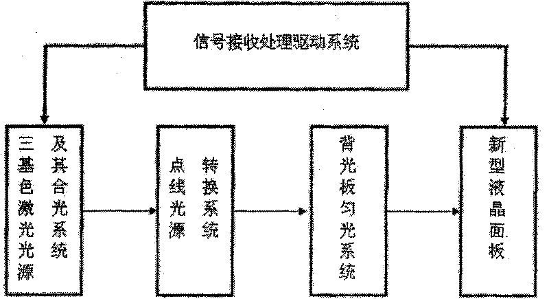
[0024] Such as figure 1 As shown, the laser backlight liquid crystal display system of the present invention includes a three-color laser light source and its light combination system, a point-line light source conversion system, a backlight panel, a liquid crystal panel, and a signal receiving and processing drive system for the liquid crystal panel.

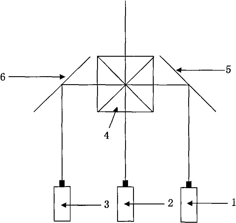
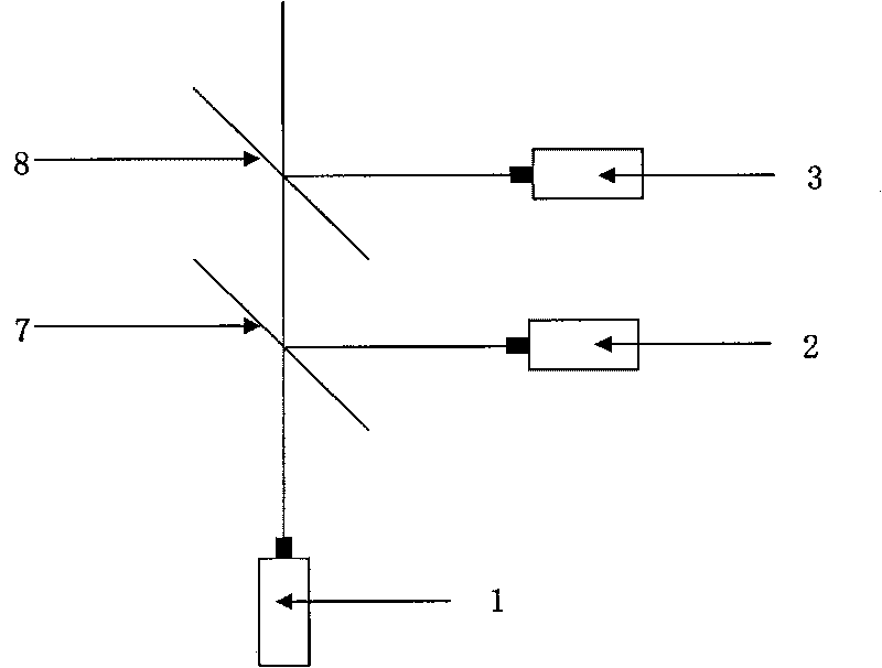
[0025] The three primary color lasers include a red laser 1, a green laser 2 and a blue laser 3. The three lasers emit light according to a certain sequence control sequence, and the output power can be controlled separately. Red light can use lasers with wavelengths of 667nm, 650nm, 640nm, and 635nm, green light can use lasers with wavelengths of 532nm, and blue light can use lasers with wavelengths of 447nm, 457nm, and 473nm.

[0026] The laser light source combination system can be used as figure 2 The shown X-shaped prism light combining system includes an X-shaped light combining prism 4 and two reflectors. The X-type li...


PUM


Abstract

The invention provides a laser backlight liquid crystal display (LCD) system which comprises a laser source with three primary colors, a light combination system, dot line light source switching system(s), a backlight plate, a liquid crystal plate and a signal receiving and processing drive system, wherein the light combination system is positioned between the laser source and the dot line light source switching system(s), the dot line light source switching system(s) is / are positioned at one or two side(s) of the backlight plate, the liquid crystal plate is positioned on the backlight plate, and the liquid crystal plate is connected with the signal receiving and processing drive system. By adopting the laser with the three primary colors, high brightness and good monochromaticity as the backlight, and the liquid crystal plate without a colored filter film, the system can realize the laser sequential display way by controlling the sequential luminescence of a laser with the three colors by timing sequence, and utilizes the characteristic of persistence of vision of human eyes to realize time color mixture, thus greatly expanding the displayed color gamut, and improving the optical energy utilization rate and the space resolution rate; furthermore, as the front of the liquid crystal plate is stuck with a view field angle expanded film, the view field can be expanded.

Description

technical field [0001] The invention relates to a laser backlight liquid crystal display system, which belongs to the technical field of laser display. Background technique [0002] Currently, liquid crystal displays (LCDs) develop rapidly and are widely used in flat panel display fields such as LCD TVs, notebook computers, and mobile phones, and have entered thousands of households. This stems from the various advantages of liquid crystal displays: no radiation, low energy consumption, small heat dissipation, light and thin, and easy to carry. The cold cathode fluorescent tube (CCFL) backlight used in traditional liquid crystal displays has the following disadvantages: (1) the cold cathode fluorescent tube contains a small amount of mercury, which does not meet environmental protection standards; (2) light leakage is common, and it is difficult to start at low temperature. The response time is longer; (3) The liquid crystal panel contains a color filter film, and the backl...

Claims


Application Information

Patent Timeline
IPC IPC(8): G02F1/13357G09G3/36F21V13/00F21V5/00F21V8/00
Inventor 王玉荣丁海生王洪君宋刚李庆华张行愚连洁万强
Owner SHANDONG UNIV
Learn More