Non-contact differential type speed encoder

A speed encoder, non-contact technology, applied in the field of speed encoder, can solve the problem of life reduction and other problems, and achieve the effect of strong adaptability

Inactive Publication Date: 2010-04-21
WUXI NEW GREAT POWER ELECTRICAL MACHINE
View PDF3 Cites 15 Cited by
  • Summary
  • Abstract
  • Description
  • Claims
  • Application Information

AI Technical Summary

Problems solved by technology

[0006] The purpose of the present invention is to provide a speed encoder with no contact between the gear and the detection element, so as to solve the problem that the life of the commonly used encoder with direct contact between the gear and the detection element is reduced due to mechanical friction

Method used


Image

  • Non-contact differential type speed encoder
  • Non-contact differential type speed encoder

Examples


Embodiment Construction

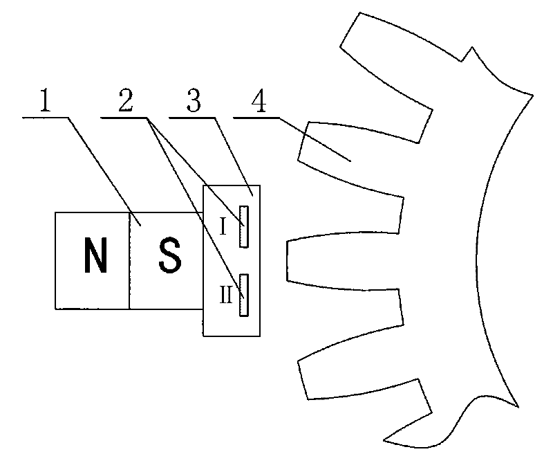
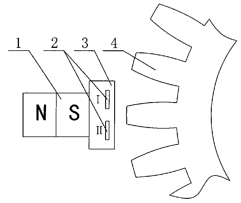
[0019] Such as figure 1 As shown, the non-contact differential speed encoder of the present invention is located on the outer side of the gear teeth of the speed measuring gear 4, and includes a magnetic element 1 and a Hall element 3, and the Hall element 3 is installed on / in the housing 2. The Hall elements 3 are symmetrically arranged, the housing 2 is made of plastic or other insulating materials, and two Hall elements 3 are arranged symmetrically.

[0020] The magnetic element 1 is located outside the Hall element 3 , the magnetic element 1 is a permanent magnet, and the magnetic field direction of the permanent magnet is perpendicular to the Hall element 3 .

[0021] The Hall element 3 outputs a high level when encountering a strong magnetic field, and outputs a low level when a weak magnetic field is encountered.

[0022] The back of the Hall element 3 uses a permanent magnet to generate a magnetic field. When the gap between the gears is aligned with the Hall element ...


PUM


Abstract

The invention provides a non-contact differential type speed encoder, which is positioned on the outside of gear teeth of a speed measuring gear and comprises a magnetic element and hall elements, wherein the hall elements are arranged on / in a shell and symmetrically distributed, and two hall elements are symmetrically distributed. The hall elements output high levels when meeting a strong magnetic field and output low levels when meeting a weak magnetic field. The backs of the hall elements generate a magnetic field by using a permanent magnet. When gaps of the gear aim at the hall elements, magnetic lines of force are dispersed and the hall elements output the low levels; and when the teeth of the gear aim at the hall elements, magnetic lines of force are concentrated and the hall elements output the high levels. Thus, the higher the rotation speed of the gear is, the higher the frequency of output signals is. Then the rotation speed of a motor can be detected. Because the gear is not in contact with a detection element, the non-contact differential type speed encoder has no mechanical friction and has long service life; and because dust, water and the like do not affect work, the non-contact differential type speed encoder has strong adaptation to environment. In addition, because the gear can be arranged outside the motor, a hot environment in the motor is avoided.

Description

technical field [0001] The invention relates to a variable frequency motor, in particular to a speed encoder applied to the variable frequency motor. Background technique [0002] In variable frequency motors, it is necessary to install an encoder on the motor to detect the speed and direction of the motor. [0003] At present, the encoder is monopolized by large foreign companies, the price is very expensive, and the proportion of the motor cost is too high. [0004] Since the detection elements of the current encoders are mostly in direct contact with the gears, mechanical friction will greatly reduce the life of the encoder. [0005] Based on the above problems, it is very necessary to develop an encoder with low cost, high reliability and long life. Contents of the invention [0006] The purpose of the present invention is to provide a speed encoder with no contact between the gear and the detection element, so as to solve the problem that the lifespan of the commonl...

Claims


Application Information

Patent Timeline
Patent Type & Authority Applications(China)
IPC IPC(8): G01P3/481G01D5/244
Inventor 华俊
Owner WUXI NEW GREAT POWER ELECTRICAL MACHINE
Why Eureka
Try Eureka