
Reinforced concrete frame abutment shallow pile plate foundation under two-driveway beam type cross connecting beam

A technology of pile-slab foundation and soil abutment, which is applied in the field of shallow pile-slab foundation of reinforced concrete frame pier under two-lane girder-type cross-link beams, can solve the problems of raw material waste and difficult work, and achieve convenient construction and lower foundation The cost and the effect of increasing the area of ​​shallow piles

Inactive Publication Date: 2010-04-21
何成俊
View PDF0 Cites 4 Cited by
  • Summary
  • Abstract
  • Description
  • Claims
  • Application Information

AI Technical Summary

Problems solved by technology

[0003] In order to solve the problems of waste of raw materials and high difficulty in construction of the cylindrical reinforced concrete foundation of the pier under the two-lane girder type cross-link beam, the purpose of the present invention is to provide a bridge pier that can not only ensure the load-bearing of the bridge pier, but also make the application safe and structural. Low-material-saving and easy-to-construct two-lane beam-type cross-link girders with reinforced concrete frame pier shallow pile slab foundation

Method used


Image

  • Reinforced concrete frame abutment shallow pile plate foundation under two-driveway beam type cross connecting beam
  • Reinforced concrete frame abutment shallow pile plate foundation under two-driveway beam type cross connecting beam
  • Reinforced concrete frame abutment shallow pile plate foundation under two-driveway beam type cross connecting beam

Examples


Embodiment Construction

[0018] The present invention will be further described below in conjunction with accompanying drawing:

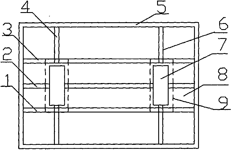
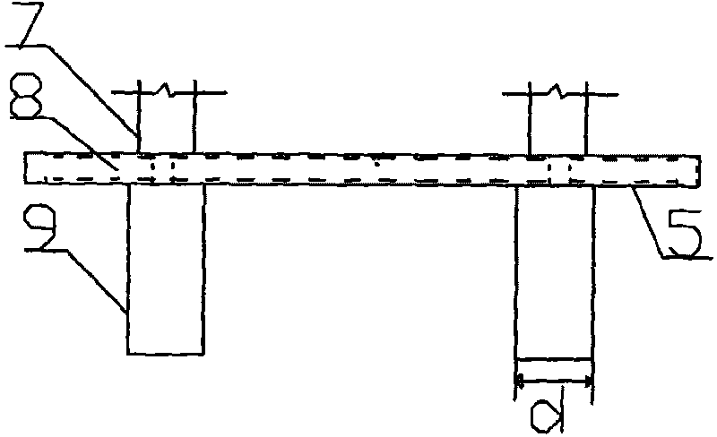
[0019] Depend on figure 1 It can be seen that the shallow pile-slab foundation of the reinforced concrete frame pier under the two-lane beam type cross-link beam is composed of a reinforced concrete slab foundation 8 and a reinforced concrete shallow pile 9 connected under the slab foundation, and the shallow pile 9 is two symmetrical Rectangular shallow piles, the frame of the slab foundation 8 is arranged crosswise by two vertical anti-cantilever beams (4, 6) and three transverse anti-cantilever beams (1, 2, 3). as one.

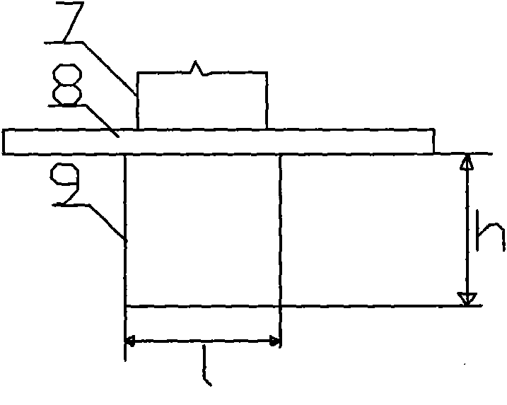
[0020] Depend on figure 2 , image 3 Can find out: described shallow pile length L=1.75 meters, wide d=1.14 meters, height h=2 meters; Shallow pile bottom area=1.75*1.14=1.995 (meter 2 ).

[0021] Depend on figure 1 , figure 2 , image 3 It can be seen that the vertical and horizontal anti-hanging beams are in the shape of a cuboid, the cross s...


PUM


Abstract

The invention discloses a reinforced concrete frame abutment shallow pile plate foundation under a two-driveway beam type cross connecting beam, which comprises a reinforced concrete plate foundation and reinforced concrete shallow piles, wherein the reinforced concrete shallow piles are connected with the plate foundation and supports the plate foundation; the shallow piles are two symmetrical rectangular shallow piles; a frame of the plate foundation is formed by crosswise arranging two longitudinally reverse suspending beams and three transversely reverse suspending beams; the periphery of the longitudinally and transversely reverse suspending beams and a closed contact beam are connected into a whole. The rectangular shallow piles meet the requirement on stability according to the design reference that a variable load generates horizontal thrust and is not upwards drawn; the load of the pile foundation is increased by the auxiliary function of the plate foundation; the piles are short and pits are shallow to be convenient for construction; meanwhile, cement and reinforcing steel bar raw materials are saved; compared with a cylindrical or rectangular entity foundation, the raw material can be saved by 35 percent; the longitudinal length of the shallow piles can be increased under the condition of unchanged distance between the two shallow piles to increase the area of the shallow piles, thereby achieving the aim of increasing the loading force of the pile foundation and being capable of solving the problem of separation of the bottom surface of a support platform 7 and foundation soil and carrying the foundation with same vertical load.

Description

Technical field: [0001] The invention relates to a bridge construction component, in particular to a shallow pile slab foundation for a reinforced concrete frame pier abutment under a two-lane beam-type cross-link beam with a width of 6-6.5 meters and a height of 10 meters. Background technique: [0002] With the construction of a network of first-class roads, second-class roads, ordinary roads and expressways, the erection and construction of bridges is also increasing rapidly. The design and construction of the reinforced concrete frame abutment foundation under the bridge span connection is also continuously improved. The current structural shape of the reinforced concrete frame abutment foundation generally adopts a separate solid cylindrical pile or a solid rectangular pile. The cylindrical pile foundation supports The maximum area is large and stable, but its disadvantages are: it is a solid pier that needs a certain depth, resulting in waste of raw materials such as c...

Claims


Application Information

Patent Timeline
Patent Type & Authority Applications(China)
IPC IPC(8): E02D27/12
Inventor 何成俊何静静范丽马建设张建旭张迪王召东陈军何超李晓飞
Owner 何成俊
Learn More