Mold mechanism driven by up-down movement arm

A mold mechanism and moving arm technology, applied in the field of mold mechanism, can solve the problems of slow running speed of the cylinder, slow running speed of the cylinder and the oil cylinder, and low lifting speed of the bottom mold, so as to improve the speed and precision of mold opening and closing, and optimize the product structure , the effect of saving space

Inactive Publication Date: 2010-04-21
张士生
View PDF0 Cites 14 Cited by
  • Summary
  • Abstract
  • Description
  • Claims
  • Application Information

AI Technical Summary

Problems solved by technology

For the mold opening and closing mechanism, the operation speed of the cylinder and the oil cylinder is relatively slow, and the production efficiency is low
If the pressure and flow of air or hydraulic oil are increased too much to increase the operating speed of the cylinder and oil cylinder, the impact will be too large during the operation of the mold opening and closing mechanism, which will easily cause vibration damage to the machine and damage to the mold.
[0005] 2. Poor mold opening and closing precision
The plastic blow molding machine requires the movement of the two closing plates to be synchronized, but the existing blow molding machines generally use power to drive one side of the closing plate and rely on the synchronization device of the gear and the rack to drive the other side of the closing plate to realize the two closing plates. The templates move towards each other synchronously. In the use of this structure, there is often a problem that the gap between the molds between the clamping templates is too large and the quality of the plastic product is affected due to the gear rack or the wear of the gear rack.
[0006] 3. The lifting speed of the bottom mold is low
The existing plastic bottle blowing machine adopts the way that the cylinder directly drives the bottom mold to rise and fall. Because the cylinder runs at a slow speed, it often occurs that the mold clamps the bottom mold that has not been raised to the right position.

Method used


Image

  • Mold mechanism driven by up-down movement arm
  • Mold mechanism driven by up-down movement arm
  • Mold mechanism driven by up-down movement arm

Examples


Embodiment 1

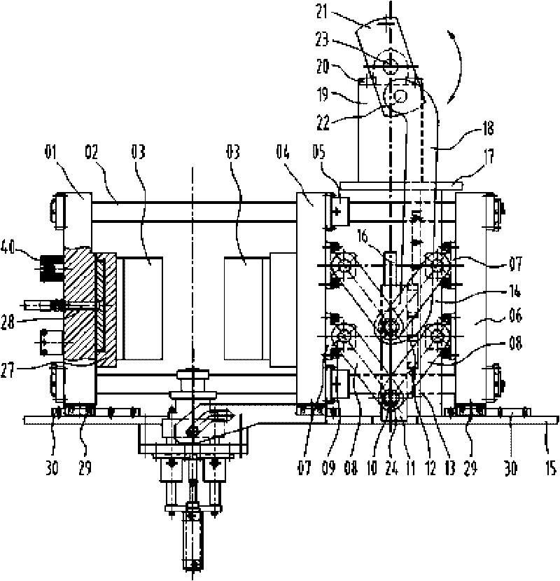
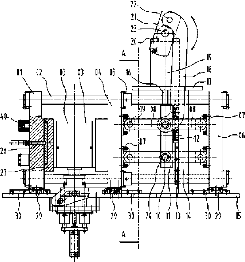
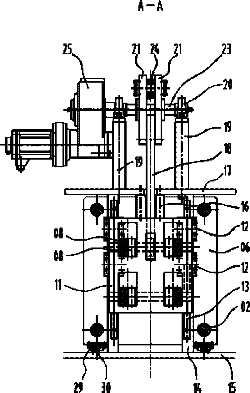
[0027] like figure 1 , figure 2 , image 3 , Figure 4 As shown, a mold mechanism driven by an up and down moving arm described in this embodiment includes a frame 15, a left template 01, a middle template 04, a bottom template 34, a connecting rod 02 and a right template 06, and the left template 01 and the right template 06 is fixed on both ends of the connecting rod 02, and the two can be linked synchronously. The middle template 04 is located between the two and is slidably arranged on the connecting rod 02 through the guide sleeve 05. Between the middle template 04 and the right template 06 A crank arm mechanism is provided, and the crank arm mechanism is two sets of parallel crank arms 08. The middle of the crank arms 08 is hinged on the lifting plate 11 through the long pin shaft 10 and the joint bearing 24, and the two ends are arranged on the crank arm support The short pin shaft 09 and the joint bearing on the 07 are hinged on the middle template 04 and the right...

Embodiment 2

[0038] like Figure 5 As shown, the mold mechanism described in this embodiment is driven by an up and down moving arm. In the case where the mold clamping speed is not high, the pneumatic or hydraulic device 26 can be used as the driving power to make the driving arm 18 move up and down. , the rest of the structure and working process are the same as in Embodiment 1.


PUM


Abstract

The invention discloses a mold mechanism driven by an up-down movement arm, which solves the technical problems of slow speed of mold opening and closing, large transverse occupied space, poor precision of mold opening and closing, small mold locking force and poor synchronism of a bottom formwork existing in the prior mold mechanism. The mold mechanism comprises a framework, a left formwork, an intermediate formwork, the bottom formwork, a connecting rod and a right formwork, wherein the left formwork and the right formwork are fixed at both ends of the connecting rod; the intermediate formwork is positioned between the left formwork and the right formwork and is arranged on the connecting rod in a sliding way; the bottom formwork is positioned below the left formwork and the intermediate formwork; a crank arm mechanism is arranged between the intermediate formwork and the right formwork; the middle part of the crank arm mechanism is connected to a lifting plate; both ends of the crank arm mechanism are connected to the intermediate formwork and the right formwork respectively; and the lifting plate is connected to a driving arm which moves up and down. The mold mechanism saves space occupation, optimizes a product structure, saves a synchronous transmission mechanism of a gear and a rack, reduces the quality problem caused by a mold-closing impact force, improves the speed and the accuracy of mold opening and closing, and has coordinative and steady operation.

Description

technical field [0001] The invention relates to processing equipment for plastic packaging containers, in particular to a mold mechanism driven by an up and down moving arm. Background technique [0002] When polyester such as PET or PP, PE, PC are used as raw materials, injection molding, heating and stretching are required to process various beverage bottles, oil bottles, medicine bottles and cosmetic packaging bottles and other hollow plastic containers through injection, stretch blowing or extrusion blowing. Blowing equipment, the stretch blowing equipment is usually called a plastic blow molding machine or a plastic stretch blowing machine, and the mold mechanism of its main part is to drive the mold to complete the mold opening and closing and provide a certain clamping force to ensure The mechanism that the middle mold is locked and does not expand. [0003] At present, the commonly used mold mechanism mainly has the following deficiencies: [0004] 1. The mold open...

Claims


Application Information

Patent Timeline
Patent Type & Authority Applications(China)
IPC IPC(8): B29C33/22B29C49/56
Inventor 张士生
Owner 张士生
Why Eureka
Try Eureka