
A computer implemented method to display technical data for monitoring an industrial installation

一种工业设施、计算机的技术,应用在显示用于监视工业设施的技术数据的计算机实施领域,能够解决有碍协作可能性等问题,达到运营和维护成本提高、高效协作、减少耗费时间的效果

Inactive Publication Date: 2010-03-24
ABB RES LTD
View PDF0 Cites 0 Cited by
  • Summary
  • Abstract
  • Description
  • Claims
  • Application Information

AI Technical Summary

Problems solved by technology

[0004] The usual way of presenting data is often done using a desktop computer screen, which limits the user to using a keyboard, mouse, etc. to interact with the 2D system to view a series of process pictures and related data
The use of desktop screens also limits the number of users, thus hampering collaboration possibilities between local and / or remote users

Method used


Image

  • A computer implemented method to display technical data for monitoring an industrial installation
  • A computer implemented method to display technical data for monitoring an industrial installation
  • A computer implemented method to display technical data for monitoring an industrial installation

Examples


Embodiment Construction

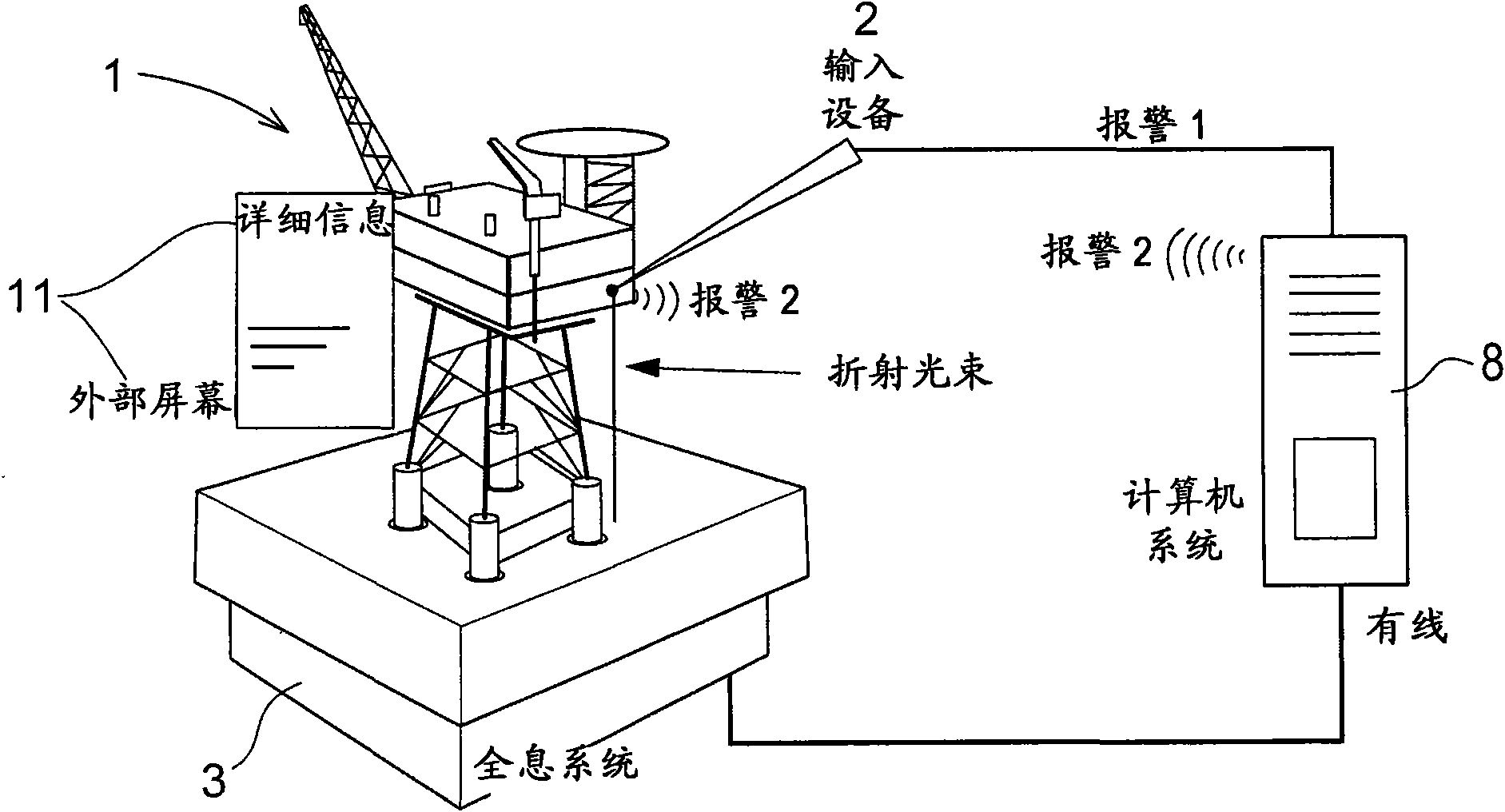
[0035] figure 1An illustrative example of an embodiment of the invention is shown. The figure shows a holographic system 3 for generating holographic images and a holographic display 1 of an oil production platform. A pointer device 2 positioned for interaction with the holographic image 1 is shown. Here the indicator 2 is shown connected by wire or wirelessly to a computer 8 which is also connected to the holographic system 3 . A separate display (external graphic screen 11 ) is schematically positioned near the holographic image 1 .

[0036] The system for implementing the method then includes a holographic device 3 generating the holographic image 1, and the device may also include: a photorefractive detector (not shown) or may configure where the user "touches" on the holographic image 1. and an input device 2 with which the user can interact with the holographic image and preferably with a data server that continuously feeds updated process information to the holograph...


PUM


Abstract

Provided is a computer implemented method to display an industrial installation, which display may also display information about an event or an alarm in the installation. The method comprises displaying an image which appears to the viewer to be a three dimensional holographic image (1) comprising a view of said industrial installation. The image may also comprise one or more points in three dimensional space and which point or points are each mapped to a corresponding point or position in said industrial installation. A pointing device for actively indicating position on the image reflectingobjects or positions in the installation is also described.

Description

technical field [0001] The present invention relates to methods and systems for remote monitoring of process equipment and process objects in industrial control systems. In particular, the present invention relates to monitoring processes in oil and gas facilities, production platforms, and processing equipment. Background technique [0002] Today, most industrial facilities and production equipment have modern efficient systems for data acquisition and storage, eg, utilizing fiber optic communications, databases, and the like. The problem, however, is that users are often unable to extract all the information hidden in the acquired data, at least in part due to the sheer volume of the process data. Even with historical data at your fingertips, users may still need assistance in locating abnormally behaving process segments, gathering information about those segments, and obtaining a diagnosis of the condition or state of the process or equipment. [0003] In the field of ...

Claims


Application Information

Patent Timeline
Patent Type & Authority Applications(China)
IPC IPC(8): G05B23/02G05B15/02
CPCG05B23/0267
Inventor C·斯库拉普S·布里恩N-A·哈尔
Owner ABB RES LTD
Learn More