
Furnace hearth of maintaining room of aluminum alloy melting furnace built by combining casting materials with precast bricks

A prefabricated brick and aluminum alloy technology, applied in furnaces, furnace components, lining repair and other directions, can solve the problems of irregular shrinkage through seams, gradual bulging, etc., and achieves a simple and fast masonry process, simple production process, and thermal expansion stress. Effect

Inactive Publication Date: 2010-03-17
SHENYANG NEU-SANKEN IND FURNACE MFG CO LTD
View PDF0 Cites 9 Cited by
  • Summary
  • Abstract
  • Description
  • Claims
  • Application Information

AI Technical Summary

Problems solved by technology

[0003] The technical problem to be solved by the present invention is to provide an aluminum alloy melting furnace holding chamber hearth built with castables combined with prefabricated bricks, so as to overcome the problems caused by the use of standard high-alumina bricks during the use of the hearth. The gradual uplift of the center and the technical problems of the shrinkage through-slits caused by the overall ramming of the hearth with high-alumina castables, so as to avoid the long and irregular shrinkage through-slits or use of The problem of gradual uplift

Method used


Image

  • Furnace hearth of maintaining room of aluminum alloy melting furnace built by combining casting materials with precast bricks
  • Furnace hearth of maintaining room of aluminum alloy melting furnace built by combining casting materials with precast bricks
  • Furnace hearth of maintaining room of aluminum alloy melting furnace built by combining casting materials with precast bricks

Examples


Embodiment Construction

[0018] The present invention will be further described below in conjunction with the accompanying drawings and specific embodiments.

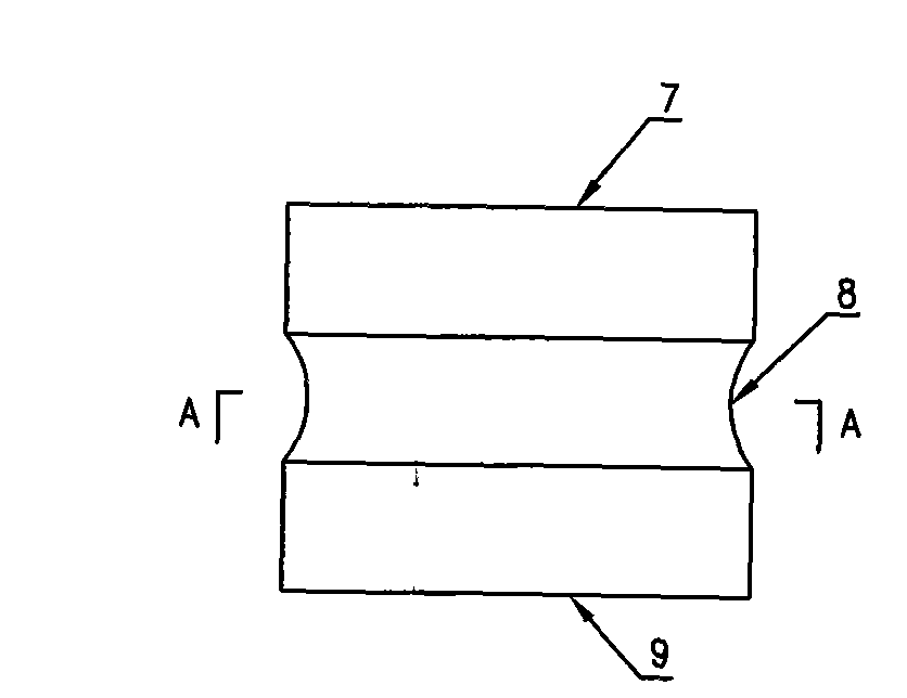
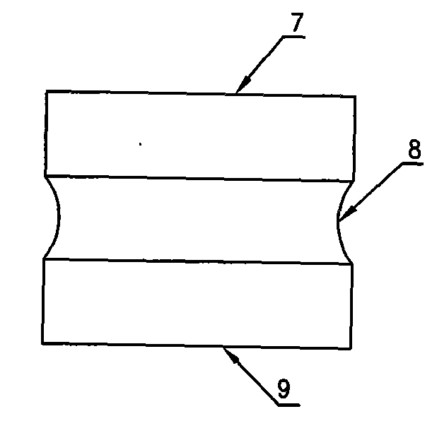
[0019] Such as Figure 5 and Image 6 As shown, the casting material of the present invention is combined with prefabricated bricks to build the aluminum alloy melting furnace holding room hearth, including a heat insulating plate layer 1, a heat insulating brick layer 2, a refractory castable layer 3 and a refractory brick layer 4, in the refractory brick layer 4 The upper part is the molten aluminum contact layer laid by high-alumina castable 5 combined with prefabricated bricks 6. The prefabricated bricks 6 have a circumferential groove 8 reserved in the middle position in the height direction, and are pounded around the prefabricated bricks 6. There is a high-alumina castable 5, and a convex-convex meshing process joint is formed between the prefabricated brick 6 and the high-alumina castable 5 in the vertical direction, and a plum blossom...


PUM

PropertyMeasurementUnit
Depthaaaaaaaaaa

Abstract

The invention discloses a furnace hearth of a maintaining room of an aluminum alloy melting furnace built by combining casting materials with precast bricks. The furnace hearth overcomes the problem of shrunken pass-through sews in the furnace hearth of the existing maintaining room. The furnace hearth is characterized in that a firebrick layer is an aluminum liquid contact layer which is paved bycombining the high alumina casting materials with the precast bricks, and the middle positions of the precast bricks are previously provided with ring-shaped grooves on the height direction. The furnace hearth has the benefits that the building process of the furnace hearth of the maintaining room of the aluminum alloy melting furnace is simple and fast due to the structure built by combining thehigh alumina casting materials with the precast bricks, and quincuncial piles-shaped technology seams are formed on the surface of an aluminum liquid contact layer due to the convex-concave-shaped technology seams are formed between the precast bricks and the high alumina casting materials on the perpendicular direction, thereby preventing the furnace hearth from having straightway sews along theheight direction thereof, preventing the baked furnace hearth from having longer and irregular shrunken pass-through sews, being capable of completely removing the thermal expansion stress in the process of dispelling under the condition that the stability of the precast bricks main body structure and the quality is guaranteed, leading the furnace hearth not to be uplifted, and obviously improving the building quality and the service life of the furnace hearth.

Description

Technical field [0001] The invention belongs to the technical field of building a tower-type aluminum alloy continuous melting furnace holding chamber hearth in nonferrous metal casting, and in particular relates to a casting material combined with prefabricated bricks to build an aluminum alloy melting furnace holding chamber hearth. Background technique [0002] The tower-type aluminum alloy continuous melting furnace came out in Japan in the late 1970s. Compared with the chamber-type melting furnace, the furnace consists of three parts: the tower, the melting chamber and the holding chamber. Fuel (oil or gas) is arranged in the furnace. ) The burner heats, melts and keeps the aluminum alloy in direct flame contact. The flow direction of the flue gas generated by combustion is opposite to the flow direction of the aluminum alloy. The aluminum alloy ingots to be melted and the returned materials are put in from the top of the tower and receive the waste heat of the flue gas....

Claims


Application Information

Patent Timeline
IPC IPC(8): F27D1/00F27D1/04F27D1/16
Inventor 丛琦季海堂
Owner SHENYANG NEU-SANKEN IND FURNACE MFG CO LTD
Learn More