
Joint lifting method used by rotor spinning frame for single-spindle feeding roller

A rotor spinning machine and feeding roller technology, which is applied to spinning machines, open-end spinning machines, continuous winding spinning machines, etc., can solve problems affecting the quality and technical indicators of high-quality medium and fine-sized yarns , to achieve the effect of improving the quality of joints, alleviating loss and damage, and improving the yarn performance of the whole machine

Active Publication Date: 2011-05-04
ZHEJIANG JINGGONG SCI & TECH
View PDF0 Cites 0 Cited by
  • Summary
  • Abstract
  • Description
  • Claims
  • Application Information

AI Technical Summary

Problems solved by technology

[0004] The technical problem to be solved and the technical task proposed by the present invention are to overcome the inability to meet the supply demand of a constant saturated fiber amount in a short time during jointing after yarn breakage caused by the inability of the prior art to feed fiber raw materials at variable speeds, which affects the rotor. To solve the defects in the quality technical indicators of spinning and producing high-quality medium and fine yarns, a method for lifting the joints of single-spindle feeding rollers for rotor spinning machines is provided

Method used

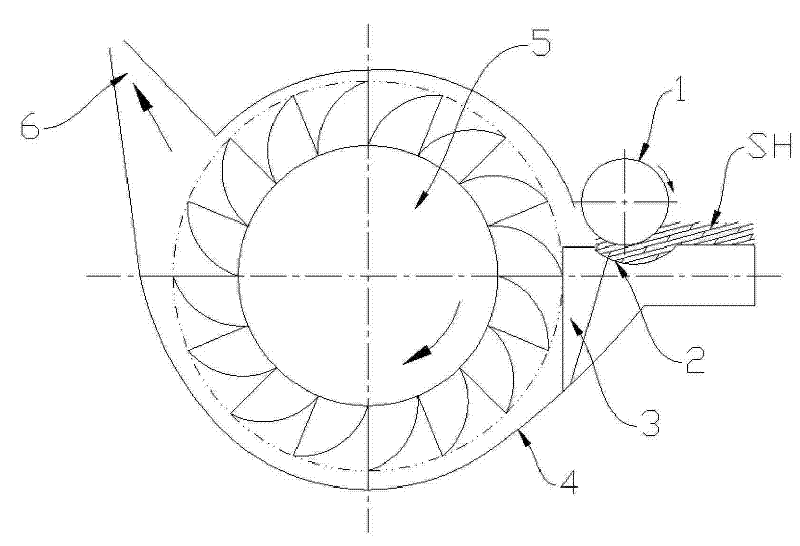
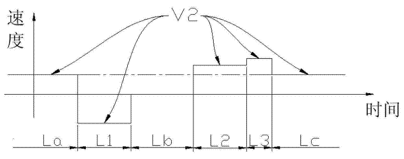

Image

  • Joint lifting method used by rotor spinning frame for single-spindle feeding roller
  • Joint lifting method used by rotor spinning frame for single-spindle feeding roller
  • Joint lifting method used by rotor spinning frame for single-spindle feeding roller

Examples


Embodiment Construction

[0029] The present invention will be further described below.

[0030] The biggest feature of the semi-automatic piecing of the rotor spinning machine is to complete the two main actions of fiber sliver feeding and yarn drawing without changing the speed of the rotor and carding roller. From the normal spinning process, we can know that only combining the twisting in the piecing process with the "rotor combined twisting" process in normal spinning is the goal of pursuing high-quality piecing. This requires the controlled feeding system to first complete the control of the amount of fibers participating in the combined twisting of the rotor, and also to control the control of the amount of fibers in the subsequent transmission, which is the transition from the joint position to normal spinning after the final yarn drawing. Provides a continuous rated guarantee of fiber flow.

[0031] High-quality joints can be distinguished from the shape and strength of the joints. The shape ...


PUM


Abstract

The invention discloses a joint lifting method used by a rotor spinning frame for single-spindle roller feeding, belonging to the technical field of spinning process. The prior art can not feed fiber raw materials in a speed-changing manner, therefore the jointing after yarn breakage can not satisfy the constant and saturated supply demand of the fiber amount within a short time, and the quality technical index of fine-quality medium and fine yarns produced by means of rotor spinning is influenced. In the method, each spindle is directly driven by an independent power to feed rollers; and in the case of yarn breakage, an electrical instruction is used for controlling the power of a spindle with broken yarn to drive the corresponding fed roller to sequentially act by following such speed orders as fiber strip withdrawal speed, high-speed pre-feeding speed, high-speed quantified feeding speed, roller feeding speed and normal spinning speed. The method can control the flow saturation degree of instant joint feeding, and even relieve the loss and damage caused by repeated static fiber bundle hammering by an opening roller after joint breakage, thereby fully improving the joint qualityand the whole-machine yarn forming performance of the rotor spinning frame.

Description

technical field [0001] The invention relates to a single-spindle independent feeding joint process of a rotor spinning machine, which belongs to the technical field of spinning process. Background technique [0002] The principle of the rotor spinning machine is that the fiber strips are fed to the rotary carding roller by the feeding roller, and the fiber strips are combed into single fibers by the carding roller, and then transported to the inner wall of the high-speed rotating rotor and placed in the condensation groove on the inner wall of the rotor. The ring-shaped strands form the yarn tail, and the yarn tail is twisted into yarn at the same time (wherein the stacking and twisting are usually together referred to as "rotor cup combined twisting") and drawn out to be wound into a bobbin. [0003] The feeding of fiber raw materials (fiber strips) on existing rotor spinning machines relies on feeding rollers, while most models use worm gear transmission. The power of this...

Claims


Application Information

Patent Timeline
Patent Type & Authority Patents(China)
IPC IPC(8): D01H4/08D01H4/32D01H4/42
Inventor 邵志军王剑浪郑光明李国刚
Owner ZHEJIANG JINGGONG SCI & TECH
Learn More